Micrometers – Shifting into High Gear
Over time, the basic handheld micrometer has evolved to include numerous contact point configurations and digital electronics. But in 150 years, the micrometer is still one of the most popular and versatile precision measuring tools on the shop floor.
Share


The basic micrometer is one of the most popular and versatile precision-handheld measuring tools on the shop floor. It provides direct size information quickly, delivers high resolution and adapts easily to many different measurement applications. The micrometer in its most basic form, having both a flat reference and a measuring anvil, has continued to improve since it was first conceived 150 years ago. The wide array of options for micrometers truly make it a universal length-measuring hand tool.
Numerous variations of alternate contact point configurations have been developed over the years to satisfy an endless number of measurement applications.
For example, ball contacts are used to measure the wall thickness of tubes and other cylindrical components. Micrometers are available with one or two ball/radiused contacts. The one ball/radius style may be used for inspection of wall thickness on tubing, while two ball/radius contacts can inspect thickness between holes. In some cases, the ball contacts can be supplied as attachments for use with a standard, flat-tipped micrometer.
Reduced spindle-style micrometers have a turned-down diameter on both the anvil and the spindle. These contacts are used to measure inside recesses where the normal diameter may be too wide to penetrate. Due to the very small contact areas of the anvil and spindle, these micrometers may take a little getting used to for users.
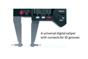
Blade contacts, still another type, are useful for measuring the outside diameter of a cylindrical part from inside a turned groove on its surface. Often these grooves can be so narrow that neither a standard nor reduced-face micrometer will fit completely into the groove. Blade contacts are very slender and flat, hence their name. They nest readily into narrow-bottomed grooves. However, the blade micrometer’s designer was challenged with an interesting problem. The spindle surface of most micrometers rotates as the micrometer barrel is turned, but a blade inside a groove would eventually be constrained from rotating. To solve this, blade micrometers have a spindle that slides along the axis of movement instead of rotating. As is the case with reduced contact micrometers, this style of micrometer calls for greater care.
A disc micrometer, designed for thickness measurements on features that have narrow clearances, is used to measure the distance between grooves on a part. The measurement contacts are relatively large, disc-like flats that extend beyond the diameter spindle and anvil. However, since these contacts have such a broad measuring surface, parallelism errors can creep into the measurement. Therefore, it is important to check the parallelism of the contacts using a precision ball on many locations between the contact faces.
Though all these types of micrometers can be very useful and versatile instruments, one problem with using them is that measurements are subject to variations from one operator to another. There are two types of influences that contribute to this variation: "feel" (or inconsistent gaging force) and subjective factors.
The micrometer is a contact instrument. Sufficient torque must be applied to the micrometer to make solid, positive contact between the part and the instrument. However, the only torque calibration in the human hand is the operator's "feel." What feels like solid contact to one operator may not feel correct to another, so the readings will be different. In order to eliminate the "feel" part of the measurement, the designers of micrometers incorporated a ratchet or friction thimble mechanism. This is an attempt to assure more consistent contact pressure and to eliminate human error.
The advent of digital electronics—and digital micrometers—also reduced most of the subjective errors that occur when measuring with the micrometer. Before, reading a micrometer thimble was always an area of difficulty for both beginners and experienced users. Switching from inch to metric mics or simply mis-reading of a line or two could mean the difference between a good or bad part. Digital micrometers eliminated this problem with their direct reading of the part size and their ability to convert from inches to millimeters if needed. New versions also offer the ability to classify the part as good or bad, with limit settings, and to collect the measured results with a data cable or wirelessly to a data documentation system.
The latest advancement to the digital micrometer is the addition of the rapid speed drive to the rotating thimble. Some versions of the sliding spindle micrometer employ a rapid drive that allows for moving the spindle 10 times faster than a standard spindle. Most micrometers have a thread pitch of 0.5 mm per full rotation of the spindle, but now versions of the micrometer have a 5.0 mm per revolution movement. The benefits of this are noticeable when measuring multiple diameters, as is typical on a shaft. This is a great increase in the point of production where it counts the most—at the point of manufacture. These rapid drive micrometers have the same sliding type of spindle as mentioned above in the micrometer for measuring grooves. The non-rotating system provides the ideal solution for measuring film thickness without twisting and damaging these delicate, thin materials during measurement.
Over the past 150 years, the basic micrometer has evolved to keep up with the demands of high-speed production and tight tolerances at the point of manufacture. We will hold our breath to see what is next for this shop-worthy tool.
Related Content
Turning Fixed-Body Plug Gages Inside Out
Fixed-body mechanical plug gages provide fast, high-performance measurement for tight-tolerance holes.
Read MoreChoosing the Correct Gage Type for Groove Inspection
Grooves play a critical functional role for seal rings and retainer rings, so good gaging practices are a must.
Read MoreHow to Evaluate Measurement Uncertainty
Manufacturing and measurement are closely coupled. An important consideration for the use of measurement results is the associated measurement uncertainty. This article describes common metrology terms and provides an example uncertainty analysis.
Read MoreHelp Operators Understand Sizing Adjustments
Even when CNCs are equipped with automatic post-process gaging systems, there are always a few important adjustments that must be done manually. Don’t take operators understanding these adjustments for granted.
Read MoreRead Next
5 Rules of Thumb for Buying CNC Machine Tools
Use these tips to carefully plan your machine tool purchases and to avoid regretting your decision later.
Read MoreRegistration Now Open for the Precision Machining Technology Show (PMTS) 2025
The precision machining industry’s premier event returns to Cleveland, OH, April 1-3.
Read MoreSetting Up the Building Blocks for a Digital Factory
Woodward Inc. spent over a year developing an API to connect machines to its digital factory. Caron Engineering’s MiConnect has cut most of this process while also granting the shop greater access to machine information.
Read More


.png;maxWidth=300;quality=90)


