3 Tips for Properly Making Form Measurements
Determining the shape of a workpiece is required in many manufacturing processes. Keep in mind these important points to ensure that you master the process.
Share


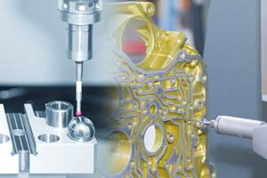
As noted in previous columns, with shrinking tolerances, form and surface conditions are features that must be controlled. Therefore, determining the shape of a workpiece is required in many manufacturing processes. It works in three steps: a dedicated form measuring machine measures the workpiece, special software filters the data and the result is determined. There are a few important points to keep in mind to ensure that you master this process safely.
Tip 1: Apply the Correct Filters
Filters are like a sieve; they can eliminate unwanted data and provide only valuable information. In order to evaluate the measurement data correctly, the correct filters in the software must be selected. Filter settings may often be part of the defined in-house measuring process. For a form measurement, filter and evaluate the data with a long wavelength, which refers to the form, and discard the data with a short wavelength.
Form filters for roundness measurements are usually specified as angular size, but not in angular degrees; rather, they are specified in a unit known as “waves per revolution,” or UPR for short. Many users choose 50 UPR as the default value. This means that the arc length is 1/50 of a circle or a section on the surface of a round object, which corresponds to 7.2 degrees. However, the arc length changes analogously to the diameter of the workpiece.
Therefore, you must always select the correct filter depending on the diameter and subsequent function of the workpiece. Depending on the choice of filter, shape defects can contain only coarse components (the workpiece is oval or “three-sided equal thickness”) or also finer components such as higher-frequency waviness.
Tip 2: Choose the Right Probe Size
When selecting the probe, one needs to account for the dimensions of the component to be tested. This is because the sensing ball at the tip of the sensing element is itself a mechanical filter. The probe must, therefore, correspond to the workpiece size and the maximum measurable number of waves per revolution. If a probe element that is too large travels on the measuring surface, it cannot fall into all valleys of the real profile. As a result, the unsuitable probe causes unwanted mechanical filtering of the data, which falsifies the measurement results.
Incidentally, many international standards for form measurement contain guides on selecting and using the correct probe element. With most modern form systems, the software can be adjusted for the probe size or stored and selected when multiple probes are used.
Tip 3: Precisely Align the Workpiece
Before measuring a workpiece’s form and position characteristics with a form measuring machine, you must first align it. With the help of the tilting and centering table, you tilt and center it so that the workpiece’s axis and the form machine’s rotation axis coincide. This prevents measuring supposed shape defects that are not there. For example, if the alignment is incorrect, a cut through an inclined cylinder may incorrectly show up as an ellipse rather than a circle. In addition, correct alignment prevents the probing point, which ideally lies exactly in the XZ plane, from wandering during the measurement.
Some form machines have an automatic tilting and centering table, which can control alignment errors very well, and you can neglect contributions to errors in roundness measurement. For example, a typical residual eccentric of 5 µm on a cylinder with an outer diameter of 50 mm leads to an additional roundness deviation of less than one nanometer. The influence of alignment errors may be greater for other features, especially those relating to position or components with small diameters. In any case, the goal is to optimize the alignment and keep the error negligibly small.
If a workpiece has a main reference, you should always align it with this reference. If no main reference exists, aligning at the points with the smallest tolerances makes sense. It is recommended to limit the skew to 10 times the numerical value of the residual eccentric (5 µm residual eccentric at 50 µm/m permissible inclination). Then, no problems will arise from the remaining skew, regardless of the distance between the measured circles.
As with any measurement, there are many factors to account for. These three basic tips will get you on the path to making meaningful form measurements.
Related Content
Rethink Quality Control to Increase Productivity, Decrease Scrap
Verifying parts is essential to documenting quality, and there are a few best practices that can make the quality control process more efficient.
Read MoreHelp Operators Understand Sizing Adjustments
Even when CNCs are equipped with automatic post-process gaging systems, there are always a few important adjustments that must be done manually. Don’t take operators understanding these adjustments for granted.
Read MoreParts and Programs: Setup for Success
Tips for program and work setups that can simplify adjustments and troubleshooting.
Read More4 Ways to Establish Machine Accuracy
Understanding all the things that contribute to a machine’s full potential accuracy will inform what to prioritize when fine-tuning the machine.
Read MoreRead Next
5 Rules of Thumb for Buying CNC Machine Tools
Use these tips to carefully plan your machine tool purchases and to avoid regretting your decision later.
Read MoreSetting Up the Building Blocks for a Digital Factory
Woodward Inc. spent over a year developing an API to connect machines to its digital factory. Caron Engineering’s MiConnect has cut most of this process while also granting the shop greater access to machine information.
Read MoreBuilding Out a Foundation for Student Machinists
Autodesk and Haas have teamed up to produce an introductory course for students that covers the basics of CAD, CAM and CNC while providing them with a portfolio part.
Read More


.png;maxWidth=150)


.jpg;maxWidth=300;quality=90)


