Automating Double-Flank Gear Testing
The form and surface finish of individual gears are becoming more demanding. Automated double-flank rolling tests are a particularly realistic measurement that simulates the behavior of the gears in operation.
Share


Gears — you’ve got to love ‘em or hate ‘em. You love them because they are part of your everyday life. They are necessary for virtually all transportation needs and any type of manufacturing tool. Micro gears are even making their way into medical devices.
With the continued advancement of electric vehicles (EVs), the interaction between gears is becoming increasingly important since there are more demands on efficiency and noise reduction. Thus, the characteristics of form and surface finish of individual gears are becoming more demanding, and new in-process testing of individual gear teeth is becoming common at the point of manufacture.
While individual gear testing is being performed, testing the interaction between gears may also be important. Functional gear testing, also known as total radial composite deviation, looks at the total effect of gear errors. This test method simulates the conditions under which a set of gears will likely operate due to the gears meshing together. The most common form of this test places the gears in a tight mesh, which produces contact on both flanks — the name of the gage to test this is aptly referred to as a double-flank gear tester. The other, less often used method of functional gear testing mounts the gears at their fixed operating distance. This method produces contact on a single flank of each of the meshing teeth. Believe it or not, the name of this type of gage is a single-flank gear tester.

Most indicator-type gear testing (rolling) instruments are manually operated. These instruments are designed for use on the shop floor to monitor gear-cutting quality. These rolling gear testers are becoming more critical as tolerances and machining requirements get tougher for metal and plastic gears.
Building a double-flank gear tester is very similar to constructing any other type of comparative gage, except that with this type of comparator, the master will be kept in the gage as part of the measuring loop. (See figure below for a typical rolling gear gage schematic.)
The work gear, or the gear being inspected, is mounted to a precision fixed arbor. A precision master gear is then mounted to an adjustable slide and brought into contact with the work gear. If variations between the work gear and the parameters of the master gear are apparent, rolling the two gears together in a tight mesh will result in a change in their center distance. This change reflects the total composite gear action caused by improper gear profile, tooth thickness variations, gear runout or pitch errors. Surface finish errors, nicks or scratches in the gear teeth can also contribute to center distance variation.
The master gear used to inspect the work gear is just like any other comparative master in that it must be manufactured to a quality level substantially higher than the work gear. Just as there are level grades for gage blocks and master balls, standards organizations have defined different quality levels for master gears. The master gear tolerances define the maximum variation for total and tooth-to-tooth errors.
Once the master and work gear are tightly meshed and running together, the composite variation must be recorded. The variation, or error, can be viewed by monitoring the position of the master gear with a comparative indicator of some type (mechanical or electric). The data can then be captured with a strip chart recorder or collected and analyzed by computer.
The most common method for evaluating the composite error is with the strip chart recorder. When the gage is run over a complete revolution of the work gear, it’s fairly easy to interpret the total composite variation and the tooth-to-tooth composite variation. To make it even easier, some gages use tolerance lines on the strip chart, limit lights on the amplifier or software limits to reduce the operator’s involvement in the measurement interpretation.
In the world of high-volume gear manufacture, manual testing may not be able to keep up with the production, or more than single-function testing may be required. Automation can test how well gears mesh or work together, speed up the process and provide more documentation of the results.
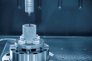
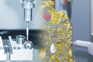
Building an automated measuring machine for double-flank gear roll testing can test the form feature concentricity deviation on the internal toothing of gears. These can be detected tactilely — measuring probe is permanently in contact with the carriage that moves the master gear and records the relative movements. The probe micron level deflections are recorded and converted by software, and Fourier analysis determines the fundamental oscillation and thus evaluates the entire measurement.
Thus, the automated double-flank rolling test is a particularly realistic measurement that simulates the behavior of the gears in operation. This enables the user to measure very quickly while still recording every tooth of the component to determine the runout deviation. The noise development of the subsequent gearbox can then be predicted based on the measurement results. This is an important aspect, particularly in electric vehicles.
Related Content
How to Calibrate Gages and Certify Calibration Programs
Tips for establishing and maintaining a regular gage calibration program.
Read MoreParts and Programs: Setup for Success
Tips for program and work setups that can simplify adjustments and troubleshooting.
Read MoreRethink Quality Control to Increase Productivity, Decrease Scrap
Verifying parts is essential to documenting quality, and there are a few best practices that can make the quality control process more efficient.
Read MoreTurning Fixed-Body Plug Gages Inside Out
Fixed-body mechanical plug gages provide fast, high-performance measurement for tight-tolerance holes.
Read MoreRead Next
Registration Now Open for the Precision Machining Technology Show (PMTS) 2025
The precision machining industry’s premier event returns to Cleveland, OH, April 1-3.
Read MoreSetting Up the Building Blocks for a Digital Factory
Woodward Inc. spent over a year developing an API to connect machines to its digital factory. Caron Engineering’s MiConnect has cut most of this process while also granting the shop greater access to machine information.
Read More5 Rules of Thumb for Buying CNC Machine Tools
Use these tips to carefully plan your machine tool purchases and to avoid regretting your decision later.
Read More


