Flexible Grinding, No Grinder Required
At the heart of this process for lean manufacturing of nickel alloy turbine blades are CNC machining centers equipped with grinding wheels.
Share


Aircraft engine manufacturing is a highly competitive industry that calls for massive capital investment and development expense against a backdrop of cyclical market need. While the complexity of the finished engine historically has meant that airlines and airframe makers have had to accept long lead times, competitive pressure is driving the search for leaner and more responsive manufacturing methods. In the United Kingdom, engine maker Rolls-Royce has responded to this challenge with a process that achieves flexible grinding of nickel alloys using grinding-wheel-equipped machining centers.
The process goes by the name "Viper," which is Rolls-Royce's acronym for "Vitreous Improved Performance Extreme Removal." The process was developed during the 1990s as a higher performance alternative to CBN superabrasive and conventional creep feed grinding techniques for machining nickel alloys. The process has been applied at a number of Rolls-Royce factories, but a turbine blade machining facility in the city of Derby is the most extensive, with ten Viper-adapted machining centers. Using this process, the facility has reduced the lead time on production of a set of high pressure turbine blades from around 100 days to 15.
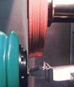
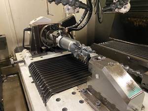
Viper grinding employs aluminium oxide grinding wheels no more than 200 mm in diameter in the spindles of specially adapted Makino or Bridgeport machining centers. The wheels are exchanged in the same way as conventional milling cutters. Up to 15 different wheel forms may be needed to machine the "fir tree" root form and "shroud" end features for a particular blade.
Rolls-Royce claims that, under the right conditions, the process is capable of stock removal at a rate of 80 cubic millimeters per second per millimeter of wheel width. That is eight times the achievable rate using plated CBN wheel technology for superabrasive machining of nickel alloys on a conventional grinding machine. The process can also finish grind at higher rates of removal than alternative methods.
Phil Hopton is managing director of Rolls-Royce Turbine Systems. He says, "We previously used creep feed grinding to machine these features. That technology was geared to large batches, with machine setup time measured in days and each blade needing to visit a number of machines. High-pressure blade production was a bottleneck process." The company examined CBN grinding as an alternative, he says, but the Viper process offered a significant improvement in performance that made it possible to change the entire approach to machining blades.
Viper's genesis traces from Rolls-Royce engineer Peter Hill noticing that satisfactory results in grinding were sometimes obtained without the use of continuous wheel dressing to maintain form and sharpness on specialized creep feed machines. Subsequent experience on a titanium milling project that used high-pressure coolant to clean the tool's cutting edge led him to consider the possibility of developing a "clean wheel" grinding process suitable for integration with conventional milling and drilling operations on a tool-changing machining center.
A 4-year development project in partnership with grinding consumables specialist Tyrolit and machining center manufacturers Makino and Bridgeport resulted in the process now in use. Perhaps unsurprisingly, the important factors proved to be the grinding consumable and the coolant. The project also dispelled any doubts about the ability of a conventional milling spindle to cope with wheel imbalance.
"There were a number of factors that we considered," says Mr. Hill. "We had to identify an open wheel bond that would not trap the micro-swarf generated by grinding. We also had to develop a coolant system and coolant formulation that would support high flow rates and high pressure, but tolerate fine filtration without foaming."
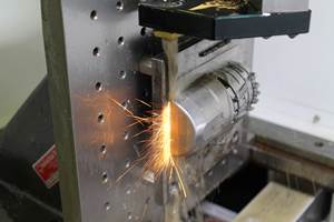
Coolant filtration is crucial to the success of Viper grinding. The process uses a specially developed nozzle to deliver coolant at 1,000 psi, at a precise angle relative to the wheel and workpiece interface. By filtering to remove particles above 10 microns diameter, the Viper process avoids erosion of the wheel's cutting edges.
During grinding the coolant keeps the chip temperature low, preventing bonding of the micro-swarf to the abrasive medium, while the jet flushes the material away. This prevents "clogging" of the wheel, eliminating the need for intermediate dressing. This in turn helps to maintain a low rate of wheel wear, resulting in acceptable "tool" life for the small diameter wheels (which in this context can be thought of as machining center tooling).
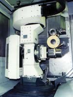
A number of build modifications are needed to adapt a machining center for Viper grinding. These relate to coolant delivery, diamond dresser installation, and sealing and guarding issues. From a process standpoint, it is necessary to maintain the same coolant delivery trajectory while grinding with up to five interpolated axes of the machine. To that end, Makino developed a two-axis CNC-controlled coolant nozzle that is mounted around the spindle nose. One axis (U) provides rotation to allow both horizontal and vertical grinding, and the other axis (V) provides for radial positioning of the nozzles to compensate for wheel wear, which can halve the wheel's diameter during a machining cycle.
Even with these modifications, however, the capital cost of the Makino A55 machining center equipped in this way is significantly lower than that of a creep feed grinding machine. Moreover, the tool-change capability allows all ground features to be produced in two operations, and the machining center's flexibility allows changeover between different components to be completed in two hours or less.
Lean Forward
With development of the Viper process completed, the challenge for Rolls-Royce was to extrapolate its advantages through the blade machining process overall.
"The technical advantages of Viper helped to drive forward a process of reform," Mr. Hopton says. "We moved from batch-based manufacture to the lean manufacturing processes adopted in the turbine blade machining facility. The working practices and methods developed for turbine blade machining also provided a template for what has become the ‘Rolls-Royce Production System.' This will be instrumental in driving down the lead time on delivery of engine sets to our customers."
Within the subcontract community serving Rolls-Royce in the U.K. there is commonly talk of the "40-day engine." Today's turbine blade machining process has played a major role in making this attainable. Of the current 15-day lead time on high pressure blades, only 4 to 5 days is actually machining time, and it is acknowledged that this could be reduced further.
Each high pressure turbine blade in an engine such as the Rolls-Royce Trent produces the same amount of horsepower as a race car engine. These blades constitute about 28 percent of the blades used in the finished engine, and the company keeps their production in house. The turbine blade machining facility at Derby has been established next to an equally high technology precision castings foundry, which produces blade blanks, as well as heat treatment facilities operated as an implant by a third party contractor. The only off-site operation is the application of specialized heat resistant coatings to the finished blade.
An expandable building at Derby houses blade machining and blade design in the same building, separated only by a glass wall. Thanks to the relatively low capital costs associated with setting up a Viper production cell, Rolls-Royce has been able to dedicate a complete line to blade development. Designers traditionally have had to "beg or borrow" time on production machinery to develop new products, but the development cell changes this. As a result, "We expect the design and production readiness of new high pressure blades to benefit," says Mr. Hopton.
Development of the manufacturing systems and methods within turbine blade machining was the responsibility of a team headed by Mark Hulands, now lean manufacturing manager at Rolls-Royce Turbine Systems. According to Mr. Hulands, an important objective was to maintain the flow of production so that the advantages accruing from the Viper process continued throughout the manufacturing route. To achieve this, the team aimed to take component setup off-line and automate it when possible. The team also sought to avoid techniques that depended on batch processing. One such technique was the previous use of zinc alloy to encapsulate the blades for easier clamping during grinding. Not only was there a queue for this encapsulation, but it also created the need for a two-stage removal process.
The factory currently comprises five identical lines (one for development and four for production) with space for a sixth. Each line is identically equipped for blade machining and nominally capable of processing any of the 18 blade types for which manufacturing routes are currently defined. The generic routing comprises four stages, which cover steps including grinding of the fir tree and shroud on a Viper cell, electrical discharge machining (EDM) of slots for seal strips and open shroud cooling features, EDM drilling of cooling holes in the aerofoil and shroud sections, wire EDM removal of the location peg, TIG welding of the core holes used in the casting process, drilling of air bleed holes, and final finishing on a CNC surface grinder.
Flexible Process
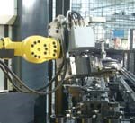
A Viper cell consists of two Viper-adapted Makino A55 machining centers and a pair of Mitutoyo coordinate measuring machines (CMMs), all served by a Fanuc robot. Input to the cell uses a roller conveyor equipped with video-based component and fixture recognition systems.
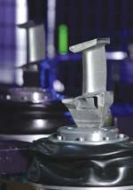
Blade castings are individually coded; they are aligned for machining in a flexible fixture using a custom-designed air gauging station. The blade locates in the fixture by a cast-on peg at the base of the fir tree section, but it remains free to move in a mechanically secured ball joint. The gauge conducts a 3D best fit analysis of the end feature positions relative to the aerofoil section of the blade, and it automatically clamps the position when all of the probed features are within 30 microns of their nominal position. The camera system on the input conveyor automatically reads the blade serial number and fixture ID, automatically archiving the data to the history file that automatically builds for each blade as it is processed.
The blade features are processed in two operations totalling 17 minutes. Op 1 takes 12 minutes where Op 2 takes 5 minutes, so the cell is balanced by having one machine performing both operations while the other does Op 1 only. Erowa clamping locations on the machine and fixture make work positioning on the machining centers and CMMs highly repeatable. All machining consists of grinding using a series of pre-formed wheels. These are set like conventional milling tools and checked against a computer generated model of the form during setup.
After Op 1 the blade is sent for checking on one of the cell CMMs. Rolls-Royce has the option of deploying automatic feature correction at this point, using adaptive machining software that automatically adjusts the parameters of the CNC program for Op 2. According to team member Terry Shaw, the process achieves a Cpk of 1.42 for feature tolerances of ± 14 microns on the fir tree root form.
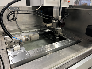
Following grinding, the components are washed, then passed to a Charmilles EDM die sinker used to produce slots for seal strips and open shroud cooling features. A novel aspect of this operation is that Rolls-Royce has inverted normal EDM practice by placing the component fixture on the quill, with the electrodes needed for machining on three fixed locations within the tank. Blades for machining are set up in stacks of four on exchangeable fixtures. Held in the machine's electrode changer, these are picked up by the quill and aligned with the required electrode using C-axis positioning. This makes it possible to complete all setting of components off-line for improved efficiency.
Similarly, setup of the blades for EDM drilling of blade cooling holes is fully automated. Each line has 12 EDM drilling machines arranged as a fully automated cell. Each machine is capable of drilling a pattern of holes using pre-formed cassettes that house multiple tubular brass electrodes. The drilling process uses deionized water as the dielectric to achieve high piercing rates.
With drilling completed, each blade is checked both visually and by video scanning to determine the presence and correct position, to within 25 microns, of the required hole pattern. The blade is then passed on for the final finishing operations.
According to Mr. Hulands, flexibility is an important advantage of this overall system. "It is possible to change over the line from one blade type to another in 2 to 3 hours," he says. "It is also technically possible to manufacture a single-blade batch, though in practice a blade set is the most likely minimum quantity."
This flexibility has implications for what Phil Hopton describes as "legacy" business—the supply of replacement blades for older engines. "Turbine blade machining is currently operated as a source for current engines, but the company has a large installed base of older engines for which spares are required," he says. "This facility provides us with a resource to do so efficiently, without the need for excessive ‘just-in-case' stocks."
About the author: Philip Capes is a U.K.-based freelance journalist specializing in manufacturing-related topics. He is a regular contributor to engineering publications in the United Kingdom.
Related Content
Dielectric Oil Dramatically Reduces EDM Maintenance
Plagued by repeated small fires that interrupted its wire EDM throughput, this cutting tool manufacturer changed its dielectric oil and both eliminated fires and reduced its oil consumption.
Read MoreHybrid Control Makes Lights-Out EDM More Accessible
This CNC enables EDMs to switch between G-code and an integrated CAM system to adapt to changing conditions and make lights-out manufacturing more attainable.
Read MoreGF Machining Solutions EDM Features Enhanced Control
The Cut F 600’s iWire function automatically identifies and adapts wire speed to changing erosion height conditions during the wire EDM process, eliminating wire breakage while reducing overall wire consumption.
Read MoreEDM Network Wire EDM Features Four-Axis Cutting
The EDMMax 434W fast-wire EDM includes four-axis cutting capability that enables it to cut 3D support structures or other shop-related parts.
Read MoreRead Next
Registration Now Open for the Precision Machining Technology Show (PMTS) 2025
The precision machining industry’s premier event returns to Cleveland, OH, April 1-3.
Read More5 Rules of Thumb for Buying CNC Machine Tools
Use these tips to carefully plan your machine tool purchases and to avoid regretting your decision later.
Read MoreSetting Up the Building Blocks for a Digital Factory
Woodward Inc. spent over a year developing an API to connect machines to its digital factory. Caron Engineering’s MiConnect has cut most of this process while also granting the shop greater access to machine information.
Read More


