What are Harmonics in Milling?
Milling-force harmonics always exist. Understanding the source of milling harmonics and their relationship to vibration can help improve parameter selection.
Share


Setting up a new milling operation has many considerations: tooling, toolholding and workholding selections; workpiece source selection (additive preform, casting, forging or wrought stock); tool path generation; tool life for hard-to-machine materials; and, of course, vibrations. Because the toolholder, spindle, machine and workpiece may be stiff but are never rigid, vibrations and chatter are important topics. Improving your understanding of their source may help reduce planning time and improve your quoting accuracy.
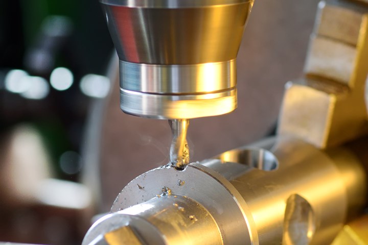
In milling, the cutting tool teeth constantly engage and disengage from the work material as the cylindrical tool rotates. At low radial depths of cut, this sequence is even more pronounced, because there are intervals when no tooth is in contact with the material and the force abruptly drops to zero. This means the force profile can resemble a train of impulses in time, where each of these tooth impacts can excite the dynamic response of the toolholder-spindle-machine work system and cause vibrations which are detrimental to the milling process. For a mental picture, imagine a mallet ringing a bell each time a tooth impacts the work.
For a flexible tool and stiff workpiece, these tooth impacts cause the tool to vibrate. These vibrations are imprinted on the work surface. The next tooth, which is also vibrating, encounters this wavy surface and the combination of the current tooth vibration and the previous tooth vibration sets the instantaneous chip thickness. This chip thickness scales the cutting force —a larger thickness gives a larger force. The force then affects the vibration and, subsequently, we have a system with feedback. This is similar to a public address system, where we hear microphone squeal when the microphone gets too close to the speaker and the volume is too high. Chatter is the milling equivalent of microphone squeal.
In cases where the cutting force is acting on a flexible, dynamic system — and the corresponding vibrations can lead to chatter and poor surface finish — harmonics is a term that I often hear referenced when describing machining dynamics. Many times, it’s used in the context of breaking up (or avoiding) harmonics.
Here’s an example: For a spindle speed of 6,000 rpm (or 100 revolutions per second) and four teeth, we have a tooth passing frequency of 400 cycles per second, or Hz. This means that the force impact repeats 400 times per second. If the radial immersion is 50% or less, then we only have one tooth in the cut at a time and we obtain a force signal that is large, then zero, then large, then zero and so on. But wait, there’s more to consider than just the tooth passing frequency!
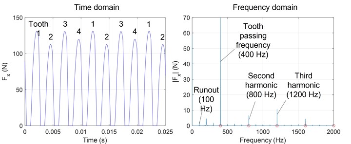
The train of impulses in time causes frequency content at not only the tooth-passing frequency, but also multiples of this frequency. For our example, this means we have frequency content not only at 400 Hz (first harmonic), but also at two times 400 Hz, or 800 Hz (second harmonic), three times 400 Hz, or 1200 Hz (third harmonic) and so on. Each of these frequencies, or harmonics, is capable of causing vibration of the flexible structure.
In addition to the multiples of the tooth passing frequency (sometimes called superharmonics), we can also have fractions of the tooth passing frequency (or subharmonics). Content at fractions of the tooth passing frequency occur due to runout in the cutter teeth. For our 6,000 rpm example, the runout frequency is 100 Hz. This is the spindle rotating frequency. Although we try to avoid runout, it is difficult to completely eliminate, so we typically see the runout frequency and its harmonics in addition to the tooth passing frequency and its harmonics. For our example, we have the potential for frequency content at 400 Hz, 800 Hz, 1,200 Hz and higher harmonics, as well as 100 Hz, 200 Hz and 300 Hz.
(Left) Cutting force in the x (feed) direction while milling at 6000 rpm using an endmill with four teeth. It resembles a train of impulses with different maximum values due to runout. (Right) Frequency content of the cutting force. The runout frequency and the tooth passing frequency and its harmonics are labeled. Photo Credit: Tony Schmitz
The figure above provides a graphic representation of the force in the time and frequency domains to help visualize the harmonics for our example. The left panel is the time domain representation of the cutting force in the feed direction, Fx. The right panel displays the frequency domain representation of the same force. In the time domain, we see the individual tooth impacts and the effects of runout. Specifically, the force for each tooth is not the same. In the frequency domain, we see the tooth passing frequency, which occurs at 400 Hz, as the largest peak. We also see its harmonics at 800 Hz, 1,200 Hz and 1,600 Hz. Due to runout, we see content at the runout frequency of 100 Hz and its harmonics of 200 Hz, 300 Hz and so on in 100 Hz intervals.
Understanding the concepts of harmonics in milling and vibrations in general can help you to not only avoid chatter and produce better parts, but also increase throughput — a topic we can visit in a future column. Until then, let’s cut metal!
Related Content
4 Steps to a Cobot Culture: How Thyssenkrupp Bilstein Has Answered Staffing Shortages With Economical Automation
Safe, economical automation using collaborative robots can transform a manufacturing facility and overcome staffing shortfalls, but it takes additional investment and a systemized approach to automation in order to realize this change.
Read More4 Commonly Misapplied CNC Features
Misapplication of these important CNC features will result in wasted time, wasted or duplicated effort and/or wasted material.
Read MoreHow to Mitigate Risk in Your Manufacturing Process or Design
Use a Failure Mode and Effect Analysis (FMEA) form as a proactive way to evaluate a manufacturing process or design.
Read MoreHow to Calibrate Gages and Certify Calibration Programs
Tips for establishing and maintaining a regular gage calibration program.
Read MoreRead Next
Setting Up the Building Blocks for a Digital Factory
Woodward Inc. spent over a year developing an API to connect machines to its digital factory. Caron Engineering’s MiConnect has cut most of this process while also granting the shop greater access to machine information.
Read MoreBuilding Out a Foundation for Student Machinists
Autodesk and Haas have teamed up to produce an introductory course for students that covers the basics of CAD, CAM and CNC while providing them with a portfolio part.
Read MoreRegistration Now Open for the Precision Machining Technology Show (PMTS) 2025
The precision machining industry’s premier event returns to Cleveland, OH, April 1-3.
Read More


.jpg;maxWidth=300;quality=90)


