There is More Than One Way to Find a Match
Three ways to control the clearance between critical-fit parts.
Share


Autodesk, Inc.
Featured Content
View More

Hwacheon Machinery America, Inc.
Featured Content
View More

ECi Software Solutions, Inc.
Featured Content
View MoreProducing a pair of parts in which the fit between them is critical (think hydraulic components or bearings) can be a very demanding task for a manufacturer. It may seem easy — by specifying that the outside diameter (OD) of one part and the inside diameter (ID) of the other be produced within 0.5 micron — but for the machinist making the parts, it’s a whole other matter. Process engineers have spent many sleepless nights trying to design manufacturing processes that will produce parts with the expectation that they will fit and work perfectly together only to find out that the process may not be as good as they think.
When the design engineer determines the tolerances for the matching IDs and ODs, this may not be what is actually critical. In these applications, as seen with matching hydraulic components, it’s really the clearance between the two diameters that is critical, as this determines how well the part performs as a whole.
There are three ways of ways of controlling the clearance between the parts. The first involves controlling the size of both parts to ensure an accurate match and full interchangeability. This method tightens the manufacturing process severely and necessitates machining to a plus tolerance on the OD part and a minus tolerance on the ID part. This could mean controlling size tolerances of an ID and OD to parts of a micron — certainly not something a manufacturing engineer with weak legs would want to undertake.
The next way may be a little more time consuming. It requires a lot of inventory to start the matching. The process is to measure and classify one of the parts to a very high level. A high-performance OD gage could be used to measure the ODs and classify them within very narrow ranges based on a tolerance that was easy to produce. Once all the ODs are classified, an air plug could be used to measure the ID of the mating part. With the ID known, the user can now select a part from the correct class OD to provide the required fit or clearance. With the ODs already measured and classified, the matching process is basic against a matching chart.
However, for some applications, these methods may not produce the tightly controlled clearance as needed. This is where air match gaging comes in. Match gaging does not measure the specific diameter of each part (although with the right instrumentation it can), but rather it measures the actual clearance (or interference) between the two parts. In the end, this can be a fantastic time and work saver when extremely tight clearances are required.
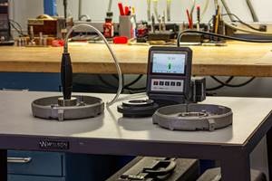
In its simplest form, match gaging uses an air gage with a two-legged manifold, one leading to an air plug, the other to an air ring. To measure a match, place the OD part in the ring and the ID part on the plug. The gage indicates the total of the clearances between the two parts and their respective fixtures. A more complex arrangement actually measures both parts, providing the actual ID and OD along with the clearance between the parts.
An advantage of match gaging is that it allows the user to produce matching parts at extremely tight clearance tolerances without actually having to achieve the same level of precision in the machining process itself.
When considering what might be easiest for the user, there are two options. The air tooling and masters could be manufactured so that the user reads the clearance between to two parts directly — achieving the clearance needed. The other method would be to design the air tooling and masters to display to the user the nominal clearance as “zero” on the gage. Either way works; it just depends on the user preference.
In addition, it is not that hard to take this process to another level. The process can be automated with a fully automatic match gaging setup, which could stage, match, assemble and package hundreds of matched pairs per hour. Feedback from the gage is used to control the processes, letting the distribution of spool ODs to move up or down to accommodate an overabundance of barrel IDs at one end of the scale or the other. Both ranges are allowed to float, chasing each other up and down the scale to assure enough matching spools and barrels to maintain production rates.
Related Content
Choosing the Correct Gage Type for Groove Inspection
Grooves play a critical functional role for seal rings and retainer rings, so good gaging practices are a must.
Read MoreHow to Evaluate Measurement Uncertainty
Manufacturing and measurement are closely coupled. An important consideration for the use of measurement results is the associated measurement uncertainty. This article describes common metrology terms and provides an example uncertainty analysis.
Read MoreHow to Choose the Correct Measuring Tool for Any Application
There are many options to choose from when deciding on a dimensional measurement tool. Consider these application-based factors when selecting a measurement solution.
Read MoreTurning Fixed-Body Plug Gages Inside Out
Fixed-body mechanical plug gages provide fast, high-performance measurement for tight-tolerance holes.
Read MoreRead Next
Measuring Tools Basics: Faster and Better
In a high-volume production environment, the cost of inspection is related to the speed with which measurements can be made and interpreted.
Read MoreClosing the Loop for Better Gaging
Gages and measuring instruments come in different shapes and sizes. Whether it be a snap gage, a bench stand, a surface-finish gage or even a form system, keeping the “measuring loop” as small or as short as possible is important for better gage performance.
Read MoreTaking A Reading on Gages
Are we taking advantage of the vast amounts of dimensional information that a gage or hand tool can produce? Certainly not if the information presented on the gage display reads only “over,” “under” or “good.”
Read More


