Share


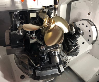
This complicated, hydraulically actuated fixture was key to the success of XL Machine’s automated turning and five-axis machining cell that produces 20 different boat propeller models.
XL Machine was a Top Shops winning company in 2017. Plus, General Manager Chris Orlowski was part of a panel discussion with representatives from the other winning shops that year at our inaugural Top Shops Conference in Indianapolis.
In checking back with him a few months ago, I learned about a neat robotic cell the Three Rivers, Michigan, shop had recently added to machine three- and four-blade cast propellers (a family of 20 part numbers) for outboard boat engines. I mentioned that holding such contoured parts for five-axis machining had to be tricky. In fact, that was the most challenging part of the project, he said.
That, my friends, is a story hook, so I scheduled a visit to learn more.
Cell Structure
Founded in 1976, XL Machine (now part of the Burke Porter Group) began as a prototype machining company. It still does prototype work today, but pairs that with production machining capability. The shop serves various customers in markets such as automotive, heavy industry, entertainment and marine.
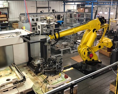
The cell includes two vertical lathes, two five-axis machines, a large robot, racks for raw material and finished parts, and the flip station shown here to enable the robot to grip the other side of the part.
At first, the customer with the propeller job turned each part’s hub in house. XL Machine would then mill either side of the contoured blades on two stand-alone three-axis VMCs and a stand-alone HMC that blended the verticals’ cuts near the hub. When its customer asked it to turn the hubs as well, creating a multi-machine, automated process seemed like a logical next step.
The photo below shows the castings as they are now received by the shop. The material is “nibral,” an alloy consisting of nickel, bronze and aluminum. It is useful for marine applications because it is durable and resists corrosion in seawater. Machining-wise, it’s said to be like stainless steel in that it’s a bit gummy.
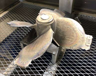
The cast propellers are made of “nibral,” a material consisting of nickel, brass and aluminum.
The U-shaped cell designed to finish these parts features four Okuma machines: two side-by-side 2SP-V760EX vertical lathes for op. 10 and op. 20 hub-turning work, and two MU 6300V five-axis machines for op. 30 and op. 40 blade-milling work. These machines are served by a large FANUC M-900ib robot.
The cell includes two multi-level racks with drawers into which the cell operator places raw castings and removes completed parts. To start the process, the robot opens a drawer to grip a raw casting by its hub. A camera mounted above the rack views the part number on tabs on the end of each blade to verify the robot is picking the correct part. (These tabs are also used for locating and clamping the parts in the five-axis machines’ fixtures.) Another camera on the robot’s arm then detects the part’s orientation so the robot properly positions the gripper without contacting the blades.
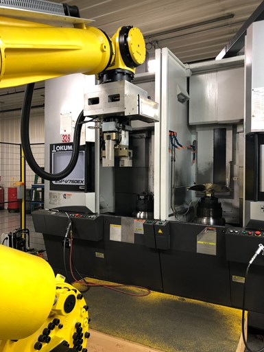
Machining starts with two vertical lathes that perform op. 10 and op. 20 turning and boring work.
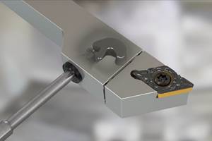
Next, the part is delivered to the op. 10 vertical lathe for internal and external machining of the hub half facing upward. The other half of the hub is secured by a custom power chuck from Co-Op Tool, a division of Hammill Mfg. The machine also uses a custom plunge tool from Cline Tool, which combines four operations into one cutter body. This is helpful because many tools for the turning and boring operations are so large that adjacent ATC pockets must remain empty to accommodate them. The custom cutter saves three ATC pockets. The machine also makes use of flood coolant and through-tool air delivery to help remove chips from the insides of the freshly machined hubs.
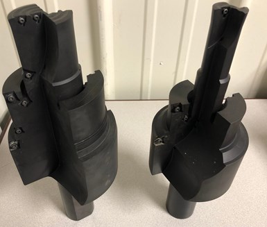
Each of these custom tools combine four operations into one cutter body. This reduces overall cycle time and frees three ATC pockets.
Once op. 10 work is completed, the robot grips the part, the power chuck disengages and the robot takes the part to a flip station. The station then lowers, and the robot, now with the gripper, facing down, grips the other side of the hub. It then takes the part to the second lathe for op. 20 hub work, which is similar to the op. 10 work. (See video below.)
Five-axis blade milling is next. The op. 30 machine mills one side of each blade, and the op. 40 machine mills the other side. This is where the trick fixturing created specifically for this application shines.
Workholding Props
In addition to the custom lathe workholding devices, Co-Op Tool supplied the two unique hydraulic workholding fixtures for the op. 30 and op. 40 blade milling work. Dave Bermudez, the company’s senior design engineer, created the fixtures. When pallets of fixtured parts shuttle in and out of machine workzones, the pallet with locating elements that seat into the machine is typically separate from the fixture. However, given the size of the propellers, and being that Z-axis space is limited in such five-axis machines, the pallets had to be integrated into the fixtures themselves. Mr. Bermudez says this reduced the height of each fixture by approximately 4 inches. But he notes it also meant that hydraulic circuits that normally would be routed internally in the fixtures had to be plumbed externally.
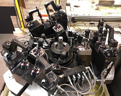
This hydraulic five-axis machining fixture accommodates 20 different part numbers, including both three- and four-blade propellers.
These fixtures feature a center collet chuck designed by Co-Op Tool onto which a propeller locates and is secured after the robot places it in the fixture. (Prior to clamping, the robot rotates the part slightly so the tabs contact stops to ensure proper positioning in the fixture.) Hydraulically actuated swing clamps from Vektek then move into position to pinch the tabs at the end of each blade. Next, spring-loaded workholding supports under each blade lock into position once they contact the underside of the part to prevent vibration during machining.
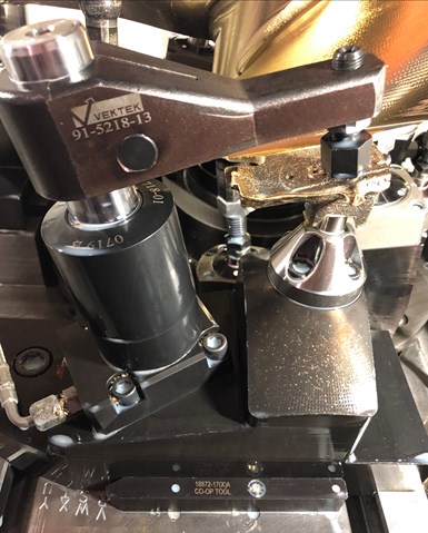
Swing clamps secure tabs on the end of each blade. Shown at the bottom, the fixture features stops that can be manually adjusted to accommodate different propeller sizes.
Because each casting varies as to how much flash or extra material it might have, the single finishing pass is preceded by a roughing pass that removes extra material. This pass might do a good bit of air cutting, but it reduces the chance of tool breakage on the finishing pass.
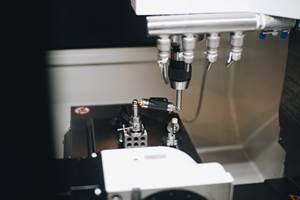
Touch probing is performed for both the op. 30 and op. 40 blade-milling operations. Once a fixture with part is loaded into a machine, a spindle-mounted touch probe locates the center and top of the hub to ensure it is properly positioned and seated in the fixture. It then touches off on the tabs to ensure the propellers are oriented correctly in the fixture. These probing routines add 10 minutes to the overall cycle time (bringing the total to 40 minutes), but the shop justifies this because they ensure proper positioning in the fixture. In addition, all cutting tools are probed to check for insert breakage before being delivered back to the ATC carousel. If it is determined that a tool did break, a redundant tool is called up and that operation is repeated.
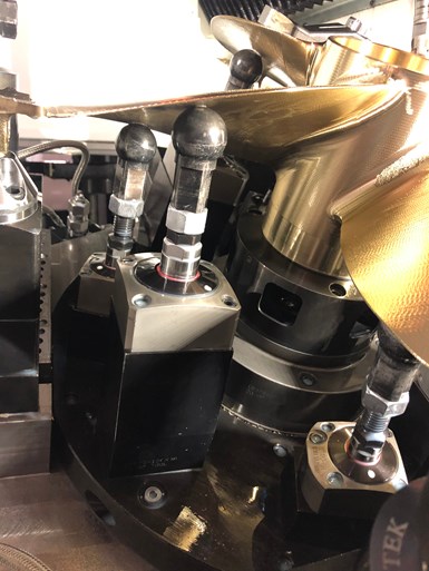
Spring-loaded devices support the bottom of the blades during five-axis machining.
The final operation is milling away the tabs on each blade. This is done with the hydraulic swing clamps still pinching the tabs. The central collet chuck on its own provides sufficient holding force for these relatively light machining operations as each tab is cut off.
A Fitting Finish
XL Machine’s propeller customer performs some subsequent polishing to the machined blades prior to assembly on its outboard engines. That said, Mr. Orlowski says the customer appreciates the quality finish of the machined blades because it minimizes polishing, especially in the corners where blade profiles transition to the hub. This required a bit of five-axis toolpath ingenuity. Specifically, a ball end mill is moved up and down the corners vertically rather than back and forth across the transition, which would leave behind multiple steps that would have to be removed. This little bit of toolpath ingenuity here takes care of the polishing.
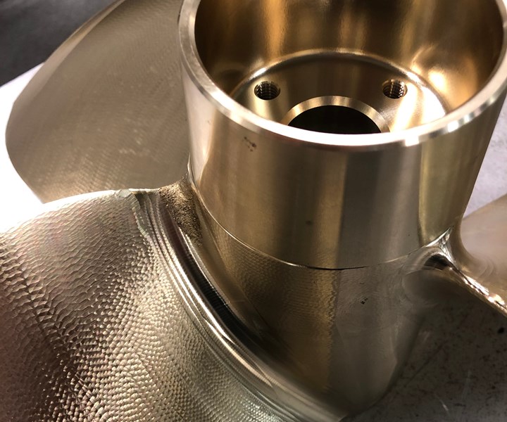
The finish achieved through five-axis machining minimizes secondary polishing.
Related Content
Inside a CNC-Machined Gothic Monastery in Wyoming
An inside look into the Carmelite Monks of Wyoming, who are combining centuries-old Gothic architectural principles with modern CNC machining to build a monastery in the mountains of Wyoming.
Read MoreQuick-Change Tool Heads Reduce Setup on Swiss-Type Turning Centers
This new quick-change tooling system enables shops to get more production from their Swiss turning centers through reduced tool setup time and matches the performance of a solid tool.
Read More5 Tips for Running a Profitable Aerospace Shop
Aerospace machining is a demanding and competitive sector of manufacturing, but this shop demonstrates five ways to find aerospace success.
Read MoreBallbar Testing Benefits Low-Volume Manufacturing
Thanks to ballbar testing with a Renishaw QC20-W, the Autodesk Technology Centers now have more confidence in their machine tools.
Read MoreRead Next
Fixturing for Five-Axis CNCs
For some high-batch-size jobs and/or very complex parts, custom fixtures designed and manufactured in house enable Powill Manufacturing and Engineering to get the most out of its five-axis machining capability.
Read MoreFixtures Dovetail with Five-Axis Automation
Along with an in-house-designed line of custom dovetail fixtures, machines with the right features for automation provide benefits for both this five-axis specialist and its customers.
Read MoreOne Five-Axis Process, 10 Elements of Automation
The new five-axis machine at Phoenix Proto has a pallet pool with loading system, but there are many other less obvious elements of automation in this precision mold-machining process that are just as essential.
Read More


.jpg;maxWidth=300;quality=90)


