On-Machine Verification Keeps Process Chain Intact
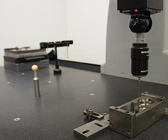
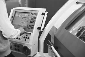
Measuring on machining centers is no substitute for this mold manufacturer's CMM. Rather, the goal of on-machine probing is to minimize downtime at individual workstations and to maximize overall throughput.
Share


Machine tools should be relegated solely to machining; leave part probing to dedicated metrology equipment. After all, a spindle not spinning is a spindle not making money, and every minute spent measuring is one less minute spent cutting. Beyond that, machine tools simply aren’t built for inspection. Even if they were, can results gathered from the same equipment that produced the measured geometry in the first place really be trusted?
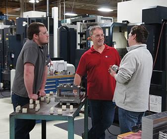
So said the skeptics at Dynamic Tool & Design when other members of the 68-employee shop first pushed to implement on-machine verification. Tellingly, there aren’t any skeptics anymore at this Menomonee Falls, Wisconsin, plastic injection mold manufacturing operation. That’s according to John Kemeny, hard-milling supervisor and one of the original champions of the new approach. “Everyone came around once they saw it in action,” he says.
Machines fitted with part probes are actually experiencing less downtime, not more, he explains, estimating overall savings at approximately four hours per day. That’s because these probes aren’t replacing the shop’s coordinate measuring machine (CMM); they’re complementing it. The idea isn’t to validate the final part, but to ensure the manufacturing process stays on track without tying up valuable, dedicated metrology resources. And although the CMM is still king when it comes to inspection, shopfloor measurements are more than precise enough to evaluate parts with typical tolerances of ±0.0002 inch.
What’s more, the shop has even bigger plans for leveraging its new probing capabilities. As Mr. Kemeny explains it, on-machine verification brings Dynamic Tool one step closer to a seamless automated process; one in which mold components proceed from one workstation to another in an unbroken chain with minimal intervention from shopfloor employees.
Indicating Isn’t Enough
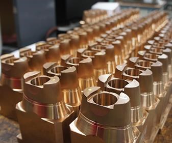
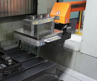
In keeping with that goal, the shop has paired 13 different machines—five graphite-cutting VMCs, four hard-cutting VMCs and four sinker EDMs—with carousel-style robots, all but one of which are Workmaster units from System 3R. Such automation isn’t just desirable for Dynamic Tool; it’s essential, Mr. Kemeny says. Any given packaging, personal care or medical industry tool coming off the 34,000-square-foot mold production area might incorporate as many as 90 identical pairs of core and cavity inserts. Ensuring that worn or damaged inserts are interchangeable without rework or hand fitting requires machining exactly to CAD models. The quicker this can be done, the quicker the mold can be assembled and tested on injection presses in the adjacent, 17,000-square-foot development center before delivery. Fast, exacting machining of a batch of parts requires fast loading/unloading and exacting setups, and robots working with pre-loaded, standardized pallets offer levels of speed and precision that no human being can match.
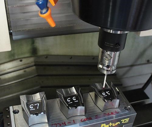
On-machine probes have long helped to facilitate that speed and precision, he says. Driven by simple macros and referencing features standard to each 3R pallet, probes mounted in the toolchangers of the shop’s VMCs ensure workpiece location offsets are error-free and available fast enough for cycles to begin almost immediately upon loading. However, indicating workpieces has never been enough to avoid interruptions in the flow of parts from robot carousel to machine workzone. Even with CAM programs prepared and the carousel loaded well in advance, ensuring operations are proceeding according to plan requires periodic, in-process measurements of critical features, Mr. Kemeny says.
No matter how robust the process planning, no matter how precise the equipment and tooling, some variation can be difficult to control on the shop floor, he explains. Tools wear; machines heat up. In fact, a spindle that starts first thing in the morning might expand enough by midday to throw a tight-tolerance parting line, shutoff or other critical feature out of specification, even with thermal compensation technology, he says. Stopping the process at every 5th or 10th part to find compensating offsets on the CMM—the busiest machine in the shop—limits capacity for lights-out runs and risks significant delays. On the other hand, to forego in-process inspection and charge ahead with a batch of components or electrodes is to flirt with the possibility of hours of rework, or even scrapped parts.
More capable machine tool probing technology gives programmers and operators another option. “My life has certainly gotten easier,” Mr. Kemeny says about his work in the hard-milling department, citing the four-hour daily downtime reduction mentioned previously. “We can do our checks right here, make any needed adjustments and just go.”
Facilitating a Seamless Process
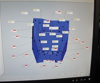
Mr. Kemeny emphasizes that the justification for the company’s new probing capabilities goes beyond downtime reductions on individual machines. Performing in-process inspections on VMCs frees the CMM for other, more critical work. The result has been improved efficiency throughout the shop. “It’s all about throughput,” sums up Andy Mears of Hexagon Manufacturing Intelligence, the supplier (via distributor Premier Machine Tool) of Dynamic Tool’s new M&H IRP40.01 machine-mounted probes, as well as the PC-DMIS software that drives both machine and CMM inspections.
Just as importantly, the CMM has lost none of its authority when it comes to passing final judgment on parts. “You still want a CMM to be your gold standard,” Mr. Mears says. “Let it do what it does best; let it be your sanity check, your final audit, the ultimate authority. In the meantime, measuring on machines can help keep things moving.”
In keeping with this mindset, Dynamic Tool’s Brown & Sharpe Global CMM is still the only resource that’s trusted to perform final, pass-fail inspections on work from every piece of equipment in the shop. That goes for not just the robot-fed VMCs, but also machines like wire EDMs and jig grinders that are less practical to automate. Likewise, the CMM is the only acceptable qualifier for first-article mold components and electrodes, which are measured at the outset of every job to verify the machining process before running an entire batch. However, the full capability of a CMM isn’t necessary for in-process checks that are more about avoiding errors than validating manufacturing sequences or generating final inspection reports for customers, Mr. Kemeny says. These are the measurements that have been relegated to the VMCs, and they are generally restricted to potentially problematic areas and tight-tolerance features that are critical to a mold’s operation.
The nature of these inspections makes them relatively simple to program for Mr. Kemeny and others on the floor, who use the same CAD models as the dedicated (and typically very busy) programming staff. After a first-article component is inspected on the CMM, it returns to the machine that produced it. There, a PC-DMIS inspection routine, posted to the CNC right alongside CAM programs, duplicates the most critical measurements in order to zero-in on discrepancies between CMM and machine. The resulting offsets ensure exacting in-process measurements for the rest of the batch.
Although these first-article checks are far less disruptive than mid-process inspections, they can still delay chip-making, particularly when the CMM is busy. However, with programs and pallets of workpieces prepared in advance, on-machine verification provides the flexibility to maximize spindle uptime by accommodating the CMM’s schedule, Mr. Kemeny says. For instance, an operator might interrupt a batch of parts to run a first article for the next scheduled job. While that first article undergoes measurement on the CMM, the first batch can continue. Leaving an extra cushion for measurement in this way increases the likelihood that the second batch of parts can undergo machining immediately after the first batch is complete. Ideally, non-cutting time amounts to only robot loading/unloading and the few minutes it usually takes to probe the next first article for comparison with CMM results.
Meanwhile, quality control personnel “can actually go home at the end of a shift,” Mr. Kemeny says. “Parts aren’t piled up as often anymore, and there’s not as much stress about what’s most important or what gets inspected first.” The effect on overall throughput has been particularly striking because so far, only two of the five graphite-cutting VMCs and two of the four hard-milling VMCs have been equipped for more than just finding zero.
What It Takes
Results often exceed expectations in shops that implement on-machine verification. That’s according to Mr. Mears, who says he regularly encounters skepticism in his role as Hexagon’s global product manager for machine tool metrology solutions. Typical hang-ups relate to not only why stopping machines for part inspection can actually be a good thing, but also what’s required to measure reliably on machining centers in the first place.
For one, it requires the right equipment. Dynamic Tool never experienced a problem with its machine-mounted touch probes until it tried to move beyond basic workpiece indicating. The problem was sensitivity. The new M&H IRP40.01 probes and the shop’s previous models operate in similar fashion: A point is registered when the force of the stylus deflecting off the workpiece is sufficient to break an electrical circuit on a three-point contact mechanism within the probe. However, triggering the previous probes required 2.31 N of force. That’s sufficient for finding zero, but not for checking whether the form or size of a critical feature is dimensioned within a few tenths, Mr. Kemeny says. In contrast, the shop’s new M&H probes trigger at only 1 N, even with longer stylus lengths. That’s closer to the performance of the probes used on the Brown and Sharpe CMM and allows for better correlation between measurements from both devices. “With this type of sensor technology, as you approach a part along a particular vector, the machine travels farther in one direction than another before the probe triggers,” Mr. Mears explains about the importance of probe sensitivity. “This is known as lobing error, and for the more robust probes you often find on machining centers, it can be really high.”
Whatever a probe’s sensitivity, it is only as accurate as the system driving it. The shop’s newer machines are equipped with linear encoders, linear motors, thermal compensation and other precision-enhancing features that simply didn’t exist in decades past. “Generally, if you’re confident about machining parts to a certain tolerance on a particular piece of equipment, you should also be able to measure those parts and control your process with at least that same level of confidence,” Mr. Mears adds.
For Dynamic Tool, maintaining that confidence has required giving machines more attention than operators had been used to in the past, Mr. Kemeny says. For instance, operators have been calibrating all the hard-milling VMCs every Monday with ceramic gage blocks to compensate for position, straightness and squareness errors inherent to the machine structure. Probes are also calibrated weekly to compensate for any runout. Whereas previous models were calibrated against ring-shaped artifacts, the M&H probes are checked against spherical standards that are permanently mounted to machine tables. Although a ring can actually be better for simple 2D measurements like determining the size of a hole, touching off against a sphere from a number of different vectors ensures sufficient accuracy for more complex 3D tasks as well, Mr. Mears says.
Other requirements for advancing on-machine probing relate more to software than hardware. For instance, compensating for ball size and tip offsets along numerous vectors is nothing less than essential for 3D measurements of profiles and angled surfaces. The difference between PC-DMIS and the software that drove the shop’s previous probes is apparent even in simpler 2D routines. Consider the aforementioned hole measurement. Whereas PC-DMIS can take as many points as the programmer deems necessary to determine diameter to a certain level of accuracy, the shop’s previous software was far more limited. As a result, size and form measurement on holes were limited to requirements of around ±0.0004 inch, (outside the range of Dynamic Tool’s typical ±0.0002-inch tolerances). Even if fewer points were sufficient, the previous software could determine only the hole’s location. PC-DMIS, in contrast, can plot hole location as it relates to other workpiece features. This capability would be critical if geometric dimensioning and tolerancing (GD&T) specifications were to call for a certain hole orientation or a certain level of perpendicularity between the hole and a specific surface.
Ready for Anything
Although the previous software wasn’t sufficient for Dynamic Tool’s purposes, the shop doesn’t truly require the full capability of PC-DMIS either. “It’s overkill to some extent,” Mr. Kemeny says, explaining that he often has to remind himself to take fewer points to keep in-process inspections as simple as possible. Beyond that, many software features simply aren’t useful on the floor at this time. For instance, three-axis VMCs aren’t capable of measuring compound angles. That requires the CMM’s rotating, tilting head.
Still, Dynamic Tool had plenty of reason to invest in more capability than it requires. This is a shop with its eye on the future, Mr. Kemeny says, and PC-DMIS opens up plenty of new possibilities. For example, PC-DMIS isn’t limited to particular workstations, as was the case with the previous probing software. Rather, it enables monitoring and sharing measurement results from any machine across an internal network. Potentially, this could open the door to pallets with radio-frequency identification (RFID) tags that transmit information from machine to machine. That information would include not just location offsets, but also critical data from in-process inspections at the previous station. “If we’re within tolerance but a sidewall is minus a few tenths, the sinker EDM downstream could make the necessary shifts without any manual intervention,” Mr. Kemeny explains.
Whatever the future holds for Dynamic Tool’s measurement capabilities, he says having PC-DMIS and new probes on the floor has markedly increased confidence in the ability to manage the process. That doesn’t surprise Mr. Mears. “Many of the typical discrepancies between measurements at the machine tool and the CMM, such as the use of different alignment schemes to datum structures, probe paths, measurement techniques, and so forth—they all go away when you’re using the same software on both devices,” he points out. “At that point, it’s much easier to sort out what’s going on in your process with more robust correlation exercises between the CMM and the machine tool.”
Related Content
Rethink Quality Control to Increase Productivity, Decrease Scrap
Verifying parts is essential to documenting quality, and there are a few best practices that can make the quality control process more efficient.
Read MoreChoosing the Correct Gage Type for Groove Inspection
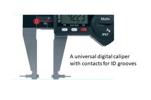
Grooves play a critical functional role for seal rings and retainer rings, so good gaging practices are a must.
Read MoreProcess Control — Leveraging Machine Shop Connectivity in Real Time
Renishaw Central, the company’s new end-to-end process control software, offers a new methodology for producing families of parts through actionable data.
Read MoreHelp Operators Understand Sizing Adjustments
Even when CNCs are equipped with automatic post-process gaging systems, there are always a few important adjustments that must be done manually. Don’t take operators understanding these adjustments for granted.
Read MoreRead Next
Building Out a Foundation for Student Machinists
Autodesk and Haas have teamed up to produce an introductory course for students that covers the basics of CAD, CAM and CNC while providing them with a portfolio part.
Read More5 Rules of Thumb for Buying CNC Machine Tools
Use these tips to carefully plan your machine tool purchases and to avoid regretting your decision later.
Read MoreSetting Up the Building Blocks for a Digital Factory
Woodward Inc. spent over a year developing an API to connect machines to its digital factory. Caron Engineering’s MiConnect has cut most of this process while also granting the shop greater access to machine information.
Read More

