Share


Autodesk, Inc.
Featured Content
View More

Takumi USA
Featured Content
View More


During the past two years, B & J Specialty has gotten used to leaving customers a little nervous after meetings.
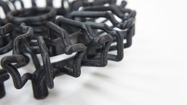
The 3D-printed metal insert in the first picture (which still needs finishing) is cooled by a serpentine network of water channels represented by this 3D-printed plastic model. The cutaway from the demo part above also reveals easy-to-print teardrop-shaped channels.
This is no concern for the Northern Indiana plastic injection mold manufacturer. So says Jarod Rauch, a design engineer who has played a leading role in the company’s drive to push metal 3D printing as an alternative to CNC machining. Education is the antidote to fear, he continues, and B & J is more than capable of proving the merits of new methods. In any case, shocked looks and skeptical headshakes are becoming less common as broader attitudes shift. “We’re seeing more large companies wanting to go this way without a manufacturer like us having to sell it,” he says.
Additive manufacturing is attractive in plastics-part molding because it facilitates conformal cooling. This is the practice of printing mold inserts with waterlines that conform to the contours of the cavity walls. By funneling water at a constant distance from the edges of the pool of molten plastic, these serpentine channels cool parts more evenly and quickly than traditional straight bores. 3D-printed inserts are particularly useful for parts with thin structures, tight corners and other hot-spot geometry that would be difficult or impossible to mold without warpage, sink marks or other defects.
If this mold manufacturer’s experience with conformal cooling is any indication, CNC machining businesses pursuing other additive opportunities may also find themselves thinking more holistically.
Results reported by B & J indicate that conformal cooling can speed injection molding cycles by 35 to 50 percent. Whatever customers’ concerns about shifting processes and materials, such gains have been increasingly impossible to ignore since the shop’s 2017 investment in a powder-bed fusion machine. “I’d say that in the next 5 years, almost all of the molds we build will have 3D-printed inserts with conformal cooling passages,” Mr. Rauch says.
However, he emphasizes that not all conformally cooled molds are created equal. About a year after purchasing the new additive machine, B & J took another step with the addition of mold-flow simulation software. Without capability to model how water flows through the channels, optimizing cooling circuit geometry would be more difficult. So would determining whether efficiency gains are truly worth the costs of change. Simulation has also become a key tool for educating new customers, some of which make it a veritable litmus test for awarding work.

Mr. Rauch says dedicated tools in Cimatron software help speed conformal cooling circuit designs, but there’s no “pushbutton” method. Every twist and turn must be plotted carefully to ensure turbulent flow — a key factor differentiating one conformally cooled mold from another.
Mr. Rauch says he never envisioned himself diving into computational fluid dynamics (CFD) when he started working at B & J 22 years ago. And if this mold manufacturer’s experience with conformal cooling is any indication, CNC machining businesses pursuing other additive opportunities may also find themselves thinking more holistically. That goes for not just the unfamiliar aspects of 3D printing, but also the broader context in which the process is performed.
Thinking Ahead
The average passerby would likely marvel at the advanced manufacturing technology within B & J’s 27,000-square-foot facility, which stands out amid the cornfields of Noble County. Beginning in a garage in the 1970s, the company’s growth can be attributed at least in part to its willingness and even commitment to expanding beyond core expertise in the pursuit of new opportunity. The existence of B & J Medical, a separate, 54,000-square-foot facility dedicated entirely to machining medical parts, is evidence enough of that.

Rows of Swiss-type lathes churn out tight-tolerance components at B & J Medical, located just a few miles from the company’s moldmaking facility. Overall, the business employs more than 200 people.
So is the company’s more recent investment in additive manufacturing. In this case, however, the process was entirely new, for the shop as well as for OEMs and molders accustomed to traditional CNC-machined inserts. Leveraging the new metal printer, a DMP PRO X 300 from 3D Systems, would require the newly educated to become educators themselves.
“(Simulation) allows me to show things in black and white, so they can see first-hand what will be in store if they decide to change.” – Jarod Rauch, B & J Specialty
Without simulation software or success stories to tout, the shop agreed to print replacements for worn, conventionally machined inserts at cost for a long-term, trusted customer, just to prove a point. As expected, conformal cooling improved injection molding speed by 30 percent while also improving part quality. Now, virtually all molds produced for this customer contain 3D-printed inserts.
However, virtually all of this customer’s molds contain CNC-machined inserts, too. Among other factors, design time, material costs, and time on the printer itself push the shop’s additive rate higher than the one it charges for CNC machining, Mr. Rauch says. Even with the right geometry, justifying a move away from machined inserts often requires careful attention to optimizing the cooling circuit, and simulation is essential to do the best work. “A good designer can come up with something that will perform well right out of the gate, but we want to offer that ‘wow’ factor,” Mr. Rauch says. “If you don’t have simulation, you’re designing in the dark.”
Stir it Up
Plastic-flow simulations help identify potential locations for 3D-printed inserts by revealing in advance where part geometry cools slowest. Plastic flow simulations can also be used to compare 3D-printed inserts with their machined counterparts.

Large plastic injection molds like this are often divided into inserts. Only problem areas warrant 3D-printed inserts, because the process remains more expensive than CNC machining.
CFD simulation tools are more important. Due to more complex internal designs, the design phase for a conformally cooled mold can last weeks, versus only days for machined inserts, Mr. Rauch says. By the time CAD files are imported into 3D Systems’ Cimatron software for design of the conformal cooling circuit, the pressure to start production can be intense. These simulations help speed the process by showing how the way water flows through the circuit will affect mold cooling.
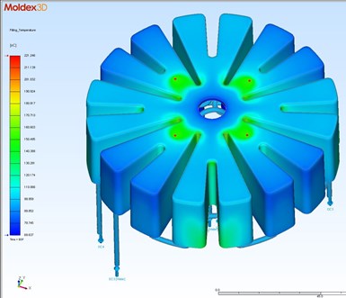
MoldEx3D shows how the conformal cooling circuit will affect the molten plastic. Image: B & J Specialty.
Most importantly, CFD analysis is critical for ensuring the channel geometry facilitates turbulent flow. Turbulent flow is the primary factor separating one conformally cooled mold from another, Mr. Rauch says. Essentially, the goal is to achieve the same cooling effect as stirring hot coffee before taking a sip. The level of turbulence within the conformal cooling channels is measured according to the Reynold’s number, which is provided by MoldEx3D’s CFD simulation tools.
“Having a good understanding of fluid dynamics is vital when designing optimal conformal passages.” - Jarod Rauch
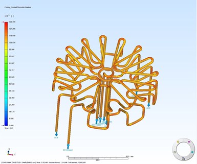
MoldEX3D shows the Reynolds value (a measure of turbulence) of the water at various points within the cooling circuit. Image: B & J Specialty.
At higher Reynold’s numbers, he explains, the flow is turbulent. That is, the water churns as it barrels through the snaking channels, creating a mixing action that prevents the outer portion of the stream from heating too quickly. At lower Reynold’s numbers, the flow is laminar: that is, straight and smooth, like water exiting a faucet. The faster the transition from laminar to turbulent flow as the water moves into the insert, the faster and more uniformly the molten plastic cools.
Various channel geometry tweaks can help accomplish this. “Adding features such as helixes and twisted elliptical passages all help in achieving high velocity and turbulent flow,” he explains. “It’s just like a garden hose. If it’s laying out straight, the water coming out the other end will most likely have laminar flow. But if you coil and pinch the hose, the flow will transition into being turbulent.
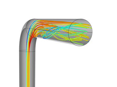
Every twist and turn of a spidery conformal cooling network is painstakingly plotted to ensure water warmed by the channel walls mixes with cooler water at the stream’s interior. The greater the turbulence, the higher the Reynold’s number, and the faster and more uniform the cooling. Image: B & J Specialty.
“Having a good understanding of fluid dynamics is vital when designing optimal conformal passages,” he continues. “For example, if you are driving 80 miles per hour down the interstate, you won’t be able to take a sharp right turn without slowing way down. But if you take an off-ramp, you can better maintain speed. This is similar to how directional changes need to happen in conformal cooling.”
Simulation also helps ensure that changes in geometry at one point in the circuit are properly balanced elsewhere. Large numbers of tunnels with differing profiles and diameters can result pressure drops or spikes, he explains. This can result in hot spots during molding that lead to part defects. He analogizes the effect to “an old farmhouse where the kitchen faucet is fine, but there’s no water pressure in the bathroom.”
Proving it Out
Success with conformal cooling has required not only getting an additive manufacturing education, but also becoming additive manufacturing educators when customers balk.
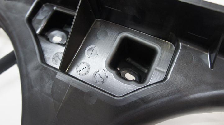
Deep, thin-walled geometry like this is ideal for conformal cooling, without which this feature might have been molded with more expensive copper inserts rather than steel to dissipate heat more efficiently.
This is largely because the benefits of conformal cooling also depend on the customer’s behavior, Mr. Rauch says. For example, differing internal geometry might leave a conformally cooled insert less robust than a machined one. Oftentimes, cooling channels lie only a few millimeters beneath the molding surface. This makes delicate handling during cleaning or other care particularly important.
Another potential problem, buildup within the twisting internal passageways, can be remedied by flushing the inserts with an acid solution. This issue also can be prevented by conducting regular flow-rate tests as part of routine maintenance. Water quality is critical for the same reason, so the company recommends closed-loop filtration systems.
All of this is solely up to the customer. However, simulation software has proven to be a critical educational aid nonetheless, Mr. Rauch says.
For one, it proves beyond a doubt that fundamental fears about mold performance are largely unfounded. A material like H13 tool steel lasts just as long whether it is forged or solidified from a bed of powder. Sintered metal also can be heat-treated just as easily, and it is just as smooth after finish-machining or EDM operations. When inserts do wear, they can be welded for repair, just like their forged counterparts.
For another, seeing results play out on screen can sway those who already convinced by the merits of conformal cooling, but are still concerned about changing maintenance procedures. “The best tools we have for convincing them are our own case studies, and our mold flow simulations and CFD analytical tools,” Mr. Rauch says. “This allows me to show things in black and white, so they can see first-hand what will be in store if they decide to change.”
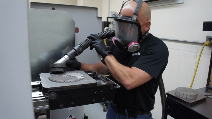
Housed in its own temperature-controlled room and requiring care to prevent inhalation of metal powder, the 3D metal printer is run primarily by Mr. Rauch. Although additive manufacturing presents a learning curve for a company that specializes primarily in CNC machined molds and medical parts, the investment proved prudent in this case.
Read Next
Generative Design Generates New Interest in a Range of Manufacturing Options
New developments in generative design can help companies make better decisions about part design by including manufacturability as a key value. CNC milling, for example, not an additive process, might come up as the better choice for making a complex part.
Read MoreCAM Simulation Gets Toolmaker up to Speed with B-Axis EDM
Software simulation helped this machine shop learn how to program its new advanced, high-tolerance wire EDM. The software also helped the shop turn job quotes around quickly.
Read MoreAdditive Manufacturing for Hard Tooling
Hybrid manufacturing is enabling tooling to be made with additive processes.
Read More


.png;maxWidth=150)


.jpg;maxWidth=300;quality=90)


