Share


The automation technology surrounding a twin-spindle CNC turning center at Superior Metal Products is impressive. However, applying effective cutting tool and workholding strategies inside that machine’s workzone was just as important to this unattended cell’s reliability and productivity.
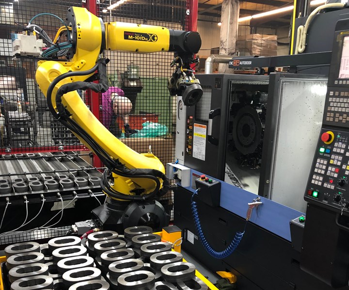
This is Superior Metal Products’ latest robot-tended machining cell. It was brought in to replace manual loading of a family of cast plates that was an unpopular job among employees.
Superior brought this robotic cell on board to replace what is perhaps the most unpopular task at its Omaha, Nebraska facility: manually loading a four-spindle, carriage-type, horizontal turning center that performs facing operations on a family of cast, ductile-iron pump components. Machining is performed dry on two of the front-facing spindles within the turning center’s enclosure while an operator loads and unloads workpieces from the other two atop the enclosure.
“Machining cast iron dry is a dirty operation,” admits Frank O’Connor, company president. “Although this particular job is a natural entry-level training assignment for new hires, the nature of this manual work, even given the machine’s dust-control system, has contributed to high turnover rates. We knew replacing this process with an automated one made sense, but we still had to justify the cost, because that machine and manual process was still fast and productive, and fixturing those parts is tricky.”
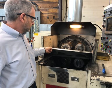
Frank O’Connor shows me the four-spindle, carriage-type machine that had run the pump component job for years. Parts were manually loaded on the two spindles outside the enclosure while machining is performed on the other two inside.
Superior brought its cell with automated part measurement/feedback-to-CNC system online early this year. (The four-spindle machine is still running pump parts for now, anyway.) Although an operator currently checks on the cell somewhat frequently since it is so new, that level of requisite attention is shrinking. Increasingly, that operator is more frequently tending other machines and performing additional value-adding tasks. Once the cell is completely dialed in, the only manual intervention should be routine machine and robot maintenance; keeping its multi-lane, in-feed conveyor stocked with fresh castings to be machined; and removing and replacing the cell’s completed parts cart.
For the most part, Superior has left the automation tweaking to its integrator, Acieta Industrial Automation. Instead, its focus has been optimizing metal removal inside the machine, and much of this work relates to tooling strategies and tool management.
Not Its First Robot Rodeo
Jim Arbogast and Norm Stoakes started Superior Metal Products in 1971. Mr. O’Connor and Randy Endorf, company vice president, became co-owners in 2012. The 50-person shop’s facility has 30,000 square feet of space and is environmentally controlled. More than half of its work is machining gray- and ductile-iron castings, much of this for the agriculture industry. Superior also machines legacy parts from billet material that were made via casting before their patterns disappeared. The company also produces hydraulic components. It has a variety of machines in addition to VMCs, HMCs and turning centers, including hobbing, broaching, grinding, lapping, welding and balancing equipment.
Automation in the shop is not new, but robots are. “We’ve used technology such as pallet pools, bar feeders, live tooling, subspindles, on-machine probing, part deburring in the machining cycle, spindle load monitoring, and tool life management to reduce manual part handling and operator intervention when machines are running,” Mr. O’Connor explains. “Given our area’s current labor shortage, we now consider all automation options and perceived level of manual task desirability with every capital expense decision. Robots represented the next logical step in our automation efforts, and our employees recognized and appreciated that.”
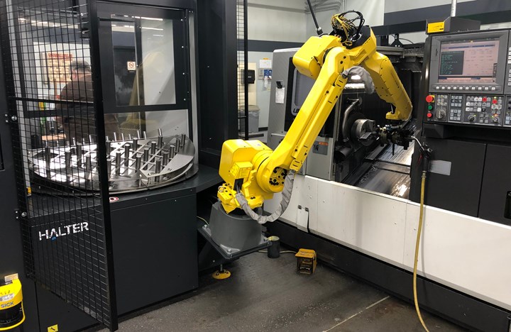
The shop’s first robot is part of this self-contained loading unit. Operators can load parts on one side of an indexing table while the robots picks parts from the other side. A laser scanner slows or stops the robot’s motion if operators get too close.
The shop installed its first machine-tending robot in July 2018. This six-axis FANUC robot is part of a self-contained LoadAssistant unit from Halter CNC Robotics designed to simplify robot programming, integration and setup. Although this unit can be deployed from one machine to another, Superior currently has it dedicated to an Okuma LB3000 EXII turning center.
In addition to the robot, the LoadAssistant includes a two-sided, 180-degree indexable table to hold raw material and completed parts. Operators can safely access one half of the table to remove completed parts and load new blanks while the robot manipulates material on the other half. The table has upper and lower grid plates with matching holes that cradle and locate material and parts. The upper plate can be adjusted higher or lower depending on workpiece height.
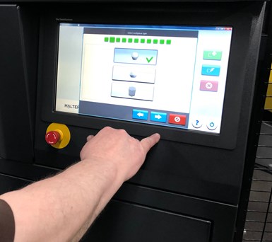
Robot programming is simplified with a conversational control.
This unit does not feature the safety fencing that commonly surrounds industrial robots. Instead, it uses a Sick laser scanner to recognize when a person approaches the robot. Entering an outer floor-space zone established around the unit slows the robot; entering an inner zone stops it. This ensures operator safety while providing unimpeded access to the machine when necessary.
The robot control’s conversational programming menu prompts operators to answer 11 prompted questions when changing over to a new job. Examples include product identification; type/part capacity of grid plates; height of top grid plates; material type (round, square or hexagonal); diameter and height of blank and finished part; and OD or ID gripping for blank and finished part.
The robot’s gripper features a spring-loaded mechanism to ensure that workpiece faces fully contact the proper jaw step once inserted into the chuck. When the chuck opens, the robot inserts the workpiece, and the spring mechanism releases to push the workpiece a maximum of 0.25 inch farther to ensure full contact with the jaw step. Chucks and jaws also have been modified with internal air-blast capability to evacuate chips. This is important because chips on jaw or chuck surfaces could cause parts to be misloaded, Mr. O’Connor says.
The pump component cell was installed soon after this initial robotic automation addition, but only after some tradeshow investigating.
Next Cell
Planning for the cell started from the inside out — that is, with the machining process itself. The shop visited IMTS 2018 to identify central machining cell elements. “Prior to the show, we pretty much decided that a turning center with two parallel, horizontal spindles facing frontward and serviced by a traditional multi-axis robot would likely be optimal for the part’s op. 10 and 20 work,” Mr. O’Connor says. “In terms of automation, however, these machines typically feature a gantry robot that delivers parts from one spindle to the other. Doosan was willing to build one of its TW2600 twin-spindle machines without a gantry loader to enable a six-axis robot to tend it, and that’s what we opted for.”
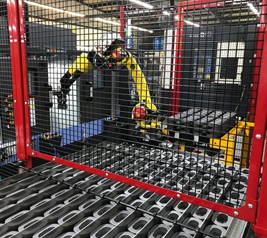
When fully loaded with pump component parts, this cell’s in-feed conveyor system can provide three hours of work for the twin-spindle turning center.
This machine features 10-inch chucks, and each spindle has its own 10-station tool turret. It’s basically two lathes in one. Because the op. 10 and 20 facing work performed on either spindle requires only one type of roughing and finishing tool, the shop can load redundant tools in each turret — seven roughers and three finishers apiece — for longer stretches of unattended operation.
Effective fixturing was also a concern. The ductile-iron parts are hollow, oval cast plates that measure approximately 4 by 7 inches and range in thickness from 0.375 to 2.25 inches. Maintaining accurate surface flatness and parallelism with each other for subsequent assembly with other pump components is imperative, however, and the real challenge comes down to preventing workholding distortion, especially for the thinner plates.
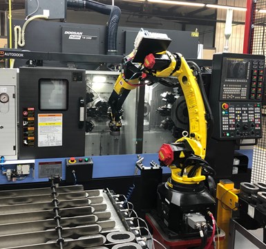
Although typically this type of twin-spindle machine has gantry loaders, Doosan provided its machine without one to enable the shop to integrate a standard industrial robot.
On the four-spindle machine from Kitako, each pair of spindles performs op. 10 and 20 work. While standard clamping is used for the op. 10 work, a magnetic chuck is used for op. 20 work to ensure that the machined face is pulled flat against it. Plus, parts must locate against two drive pins on the magnets to within 0.003 inch to avoid shifting or dislodging entirely during machining. While magnetic chucks could have been used on the twin-spindle cell machine, Superior discovered that pull-back chucks from Samchully would grip the parts and draw them against a stop to ensure proper seating without distortion. They also included air-gap sensing technology to confirm parts were properly loaded. In fact, these chucks are used on both machine spindles, not just the op. 20 spindle.
As for the external automation, Acieta designed a single, 12-lane in-feed conveyor to supply the cell with raw castings for machining. Each lane has a sensor at the end that detects the presence of a casting for the robot to pick. If a casting is not detected, the conveyor will advance to bring more forward. The conveyor belt is made of material that slips under castings lined up and in contact with one another. This prevents the workpieces from lifting off the conveyor and piling up. If none are detected in any lane, the conveyor will run for 30 seconds because an operator might have just started to load a new batch. If the sensors still don’t detect castings after that half minute, an alarm signals that the conveyor is empty. When filled, the conveyor has the capacity for approximately three hours of machining work, as does the cart that receives completed parts.
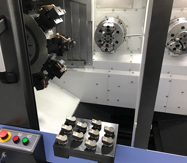
Each of the cell machine’s two spindles has a 10-station turret. The shop uses quick-change toolholder system for fast tool changes and 3D-printed trays to hold 10 fresh tools.
As long as the conveyor remains stocked with new castings, machining is interrupted only after all 20 tools in the machine have been consumed. For fast tool changeovers, the shop uses Kennametal KM quick-change toolholders. It also created ABS plastic trays using its Lulzbot TAZ-6 desktop 3D printer to carry 20 new toolholders loaded with fresh or indexed inserts to the machine. Trays rest on the lip of the machine enclosure for easy operator access. Total tool changeover time is approximately 15 minutes.
The Kennametal cutting inserts used to machine the ductile iron in this cell were designed to machine stainless steel. Unlike the standalone machine that face-machines parts dry, the Doosan machine uses coolant, primarily for dust control. The shop found that the insert used in the dry process does not perform well when machining wet.
“We tested 10 or so different inserts to find one that offered long, predictable tool life,” Mr. O’Connor explains. “Due to per-piece casting variation and the facing operations’ interrupted cuts, an insert edge might last 30 or maybe only seven minutes. Ultimately, we found that an insert designed for a completely different material provided the most consistent tool life. We now can confidently specify 25 minutes of insert use before the control changes to a redundant tool.”
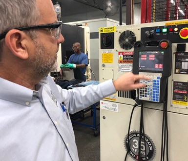
Changeover is as simple as entering a four digit number (last four of the part number to be machined) into the cell controller. That number is sent to the lathe’s CNC each time the robot loads a part and is used to set all variables associated with the part to be machined.
Cell Coreography
The machine is tended by a six-axis, M10iD12 FANUC robot that uses two ID grippers to pick castings from the in-feed conveyor and deliver them to the lathe’s left spindle (left, if you were facing the machine). It first removes a completed op. 10 part using its empty gripper, then installs the new casting held by the other gripper into the chuck. The robot takes the op. 10 part to a flipping station, secures that part in one gripper, uses its other gripper to pull the completed part out of the op. 20 spindle, and installs the op. 10 part into that spindle. The completed part is then delivered to a pedestal gaging station, designed by Superior, where Keyence GT2 digital contact sensors actuate downward to measure part height. (Parts are 100% inspected here.) Compliant parts are stacked on the cell’s completed parts cart. Those that do not meet measurement specifications are delivered to a staging area for possible rework.

Parts in this cell are 100% inspected after op. 20 work. Digital contact sensors in this gaging station actuate downward to measure part height. Measurement data is sent to the machine’s CNC to make an automatic tool offset adjustment if the part is 0.0005 inch taller than nominal.
The gaging station does more than identify parts that are in or out of specification. It also provides feedback to the machine control to adjust tool offsets via conditional statements in the CNC program. If part height measurement is more than 0.0005 inch larger than nominal, a tool offset change will automatically be made.
Where Does 3D Printing Fit In?
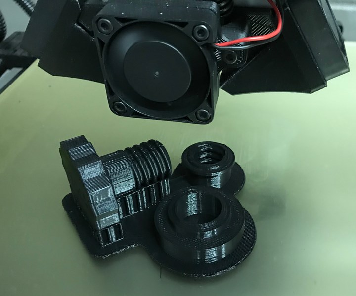
Toolholder trays for the pump component cell are not the only helpful items produced on the shop’s 3D printer. Many support the shop’s 5S workplace organization efforts. For example, hanging on the cell’s fencing are printed items to hold Allen wrenches, a broom, a dust pan, a cleaning bottle, a grease gun, job travelers and so on. The shop also prints job-specific trays for gages and other devices. Plus, it has created a unique plug to insert into drawn-over-mandrel (DOM) tubing it machines in bar-fed turning centers. It prints the three components for this plug — threaded knob, expander and nut — which, when assembled with the properly sized O-ring, can be installed in the end of a DOM tube to seal and prevent chips and coolant from being sprayed back into the bar feeder (see sidebar in grey box below).
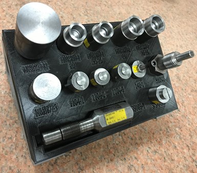
Superior is using its 3D printer to create standard brackets to hold job-specific trays for hand gages, tools, etc. that can be removed and replaced as needed.
In a sense, 3D printing represents yet another form of shop automation. Once a CAD file is created, a print can begin and run to completion without intervention. That said, like other automated processes, 3D printing isn’t without its own learning curve. For instance, Superior initially printed the threaded knob of its DOM plugs standing on its end. However, it found that the laminations of the printed, threaded component often would shear when tightened into the nut. It now prints that component supported on its side to prevent that from happening.
Related Content
4 Commonly Misapplied CNC Features
Misapplication of these important CNC features will result in wasted time, wasted or duplicated effort and/or wasted material.
Read MoreA History of Precision: The Invention and Evolution of Swiss-Style Machining
In the late 1800s, a new technology — Swiss-type machines — emerged to serve Switzerland’s growing watchmaking industry. Today, Swiss-machined parts are ubiquitous, and there’s a good reason for that: No other machining technology can produce tiny, complex components more efficiently or at higher quality.
Read MoreSecond B-Axis Improves Efficiency of Swiss-Type Machining
A highly stable, fully programmable B-axis on the subspindle of Nomura DS’s 20J3XBTC enables users to more quickly machine complex parts complete.
Read MoreInverting Turning and Five-Axis Milling at Famar
Automation is only the tip of the iceberg for Famar, which also provides multitasking options for its vertical lathes and horizontal five-axis machine tools.
Read MoreRead Next
Can Vision and Artificial Intelligence Make Every Robot Collaborative?
That is the aim of this Boston-area startup. Last year, it came to market with technology to make even fast and powerful industrial robots safe to approach. The technology promises to eliminate the need for guarding around them — safety measures that might not be as safe as you think.
Read More3 Mindset Changes for Lights-Out CNC Machining
Expanding capacity into the unattended hours calls for counterintuitive new ways of thinking about the work.
Read MoreIn Lights-Out Machining, Part Loading Is Not the Problem — Here is How This Shop Handles Unloading
Correct unloading of the parts affects part quality as well as the capacity of the unattended machining system. Here is more of the experience from our “168” shop.
Read More




.jpg;maxWidth=300;quality=90)


