How Gaging Flexibility Saves Time and Effort
A gaging system that matches the way parts are made can save you both time and effort.
Share


ECi Software Solutions, Inc.
Featured Content
View More
Takumi USA
Featured Content
View More

Autodesk, Inc.
Featured Content
View More


At the very basic level, a manual gage is created with the specific goal of making it easier to stage and gage a part, reduce operator error, and ensure the best performance for the measuring task at hand. Such designed-for-the-application fixturing can significantly reduce effort for the user and reduce the time required to complete the measuring process.
Another way to save time is to make multiple checks in sequence. A common shopfloor practice is to provide a series of tools for the operator to use in a specialized gaging station. Often, these gages can be connected to a gaging computer through a wired or wireless network. The computer can then provide a guided gaging sequence for the operator, indicating which gage to use in the gaging process, helping him or her make the measurement with pictures/instructions, and collecting the data to provide feedback for part qualification. These workstations and guided sequences provide a sort of automation to give the user clear steps to follow, while all data collection and part qualification is done automatically, thus reducing operator involvement and measurement time.
Measuring time can also be greatly reduced by building a gage that makes multiple measurements at the same time. A custom gage designed to measure multiple diameters, lengths and runouts on a shaft, for example, provides easy loading, no operator influence on results and part qualification within seconds.
Many gage builders have begun using what are known as “standard elements” to create multiple dimensional measurement systems configured for a particular part. The use of these standard elements allows a custom gage to be created in a relatively short amount time for fast implementation, and then potentially allows the gage to be reconfigured for families of similar parts. With this multiple dimensional measuring solution, the gaging sequence is compressed into a one-shot measuring cycle.
The standard elements in these systems tend to be designed with the same robustness as the components used in a custom gage design; the only difference is that there is a common mounting scheme for the items, standard measuring heights, and the ability to use a wide range of transfers, contacts and sensing devices. Therefore, with knowledge of these elements in hand, the gage builder or user can shop from a list of stock items and create a custom gage designed for the specific task at hand, sometimes in days, and usually at a fraction of the cost of a custom-designed part gage.
Gage builders also are employing this build-to-task concept for the measurement and data-collecting part of the solution. The common practice is to use an off-the-shelf computer-based gaging system, often loaded with multiple input capabilities, some I/O, and very capable and powerful measuring software. Many of these software packages bundle together the measuring functions, basic programmable logic control and statistical capabilities in one system. This provides a lot of capabilities, but along with these comes a degree of complexity, often a bit more than the standard gage control technician can handle.
A recent trend being offered by gage builders is a concept similar to the standard mechanical elements, but using electronic modules and software, that allows users to put together a gaging and display package with only the capabilities needed to do the job. This modular electrical concept saves on hardware and software cost and allows the user to build a gaging system tailored to the specific task—nothing less and nothing more.
These systems start with a flexible but simple-to-use software module for taking various gaging inputs and displaying results to the user. The concept often used with these software packages is to take “programming” out of the equation. Rather, measuring tasks are created with a series of icons related to the task at hand. For example, icons can represent a simple one-probe length check or two-probe differential check, or a complex eight-probe concentricity calculation. Thus, all the user needs to do is select the task icon and start measuring parts.
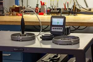
The second part of this standard electronic elements solution is a series of modules that are linked together to create the desired measuring task. These modules for linear variable differential transformer (LVDT) or digital probes, air tooling, and I/O capability are locked together and provide the input data to the modular software via a simple USB interface. The customer only needs those modules that match the application, and since these run on virtually any PC, the user can decide on the solution that best fits his or her application, even using existing manufacturing PCs to do the gaging as part of the operator’s workstation.
In today’s fast-paced manufacturing operations based on flexibility and short runs of precision parts, a gaging system that matches the way parts are made may be the solution to solve your requirements.
Related Content
What are Harmonics in Milling?
Milling-force harmonics always exist. Understanding the source of milling harmonics and their relationship to vibration can help improve parameter selection.
Read MoreHow to Mitigate Risk in Your Manufacturing Process or Design
Use a Failure Mode and Effect Analysis (FMEA) form as a proactive way to evaluate a manufacturing process or design.
Read More4 Steps to a Cobot Culture: How Thyssenkrupp Bilstein Has Answered Staffing Shortages With Economical Automation
Safe, economical automation using collaborative robots can transform a manufacturing facility and overcome staffing shortfalls, but it takes additional investment and a systemized approach to automation in order to realize this change.
Read MoreHow to Choose the Correct Measuring Tool for Any Application
There are many options to choose from when deciding on a dimensional measurement tool. Consider these application-based factors when selecting a measurement solution.
Read MoreRead Next
5 Rules of Thumb for Buying CNC Machine Tools
Use these tips to carefully plan your machine tool purchases and to avoid regretting your decision later.
Read MoreSetting Up the Building Blocks for a Digital Factory
Woodward Inc. spent over a year developing an API to connect machines to its digital factory. Caron Engineering’s MiConnect has cut most of this process while also granting the shop greater access to machine information.
Read MoreBuilding Out a Foundation for Student Machinists
Autodesk and Haas have teamed up to produce an introductory course for students that covers the basics of CAD, CAM and CNC while providing them with a portfolio part.
Read More


