Don’t Sweat the Setup: Probing the Position of Complex Workpieces
This manufacturer uses a software tool to tailor the machining program to the location and orientation of each contoured part.
Share


Aerodine Composites supplies parts that, until recently, the company would not have thought to produce through CNC machining.
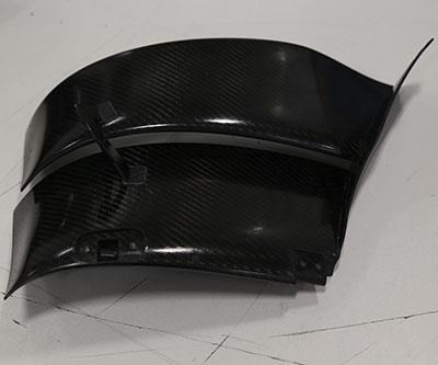
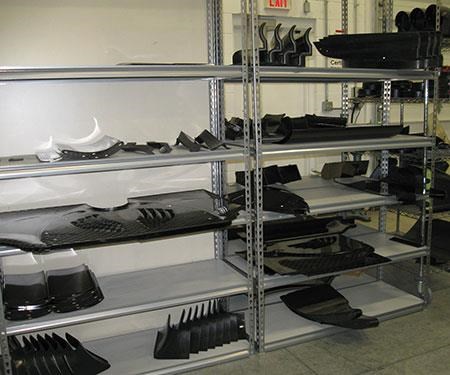
This Indianapolis manufacturer produces carbon fiber reinforced plastic (CFRP) body components for IndyCar racers. The aerodynamic parts are often so curvy, their quantities are so small, and the actual machining is so slight that setup time seemed likely to eliminate any chance of efficiently machining them with a programmed CNC cycle. Instead, this company has historically finished the parts by hand, using drilling and trimming jigs to guide the manual cuts.
But the limit to this manual approach was reached soon after Aerodine recently became a supplier for a major auto maker, manufacturing the aero kits (aerodynamic outer bodywork) for this car company’s racing-industry business. As part of the aero kit design that this customer developed, metal is placed within the core of CFRP parts to hold fasteners. That metal is sometimes titanium. Aerodine had no effective way to drill by hand through the titanium-reinforced sections of the composite parts.
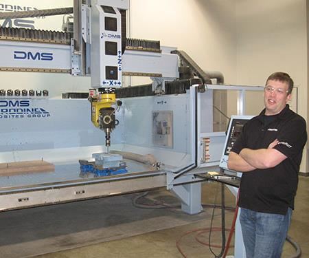
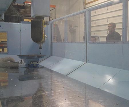
By this point, though, the company did have a five-axis CNC router. It had purchased the machine tool (from Diversified Machine Systems) to improve its lead times in obtaining patterns—tools that are part of the process for making CFRP parts. Speeding up pattern-making was one of the changes the company made to win the auto maker’s work. Could this machine therefore also be used to mill and drill the difficult CFRP parts?
Maybe yes. The challenge was to do this in a way that was cost- and time-efficient. Fixturing was not the answer. Creating precise, sophisticated holding fixtures to quickly and accurately clamp every one of these parts would make no sense, because there are more than 100 part numbers per kit, most of which are produced in quantities of only 50 before the racing season ends and new designs are developed. The fixtures would be discarded too quickly.
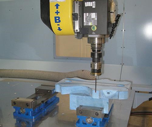
The answer Aerodine found instead lets the company rely on less sophisticated fixtures that are easier to discard. The company makes inexpensive tooling out of RenShape modeling board—fixtures that do little more than support the part. The tooling doesn’t don’t need to precisely position the part, because Aerodine relies on probing, not exact physical positioning during setup, to achieve the necessary precision.
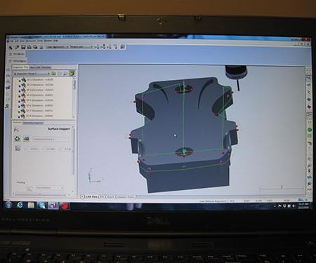
Specifically, the company uses the “PartAligner” feature of Delcam’s PowerInspect software to precisely rotate a machining program’s XYZ coordinate system to match the orientation of the workpiece as determined from the probing measurements. The machining program created in PowerMill (also from Delcam) is then re-posted to match the coordinate system based on the actual measured position of the part.
In other words, the CFRP part’s precise location and orientation now do not matter. Aerodine’s system adapts the machining program to find the part. The question of saving setup time is no longer important, because setup has become a quick and easy step.
Company machining manager Kyle Castor oversees and programs the router, and he performs this setup—or lack thereof. For each aero kit part machined, he bolts a vise to the table, clamps the RenShape fixture in the vise and places the workpiece into position on this tool without any need for minute, careful adjustment of vise, fixture or part. The setup is simple, but the reason it is simple lies in the measures he has taken long before this moment. For each part, Mr. Castor has devised a probing routine with sufficient measurements to capture that part’s precise location and orientation. Quickly running that probing routine is therefore the final step each setup requires. The PowerInspect software mathematically fits the probe measurements to the part’s CAD model in order to locate the part in space.
Mr. Castor recognizes his company’s parts are particularly good candidates for this probe-and-align approach to setup. The parts here frequently lack straight lines, and they have short product lives. Even so, he says it surprises him that this method of locating the part is not used more pervasively. In this application at Aerodine, the shop has discovered that software can almost entirely take the place of the steps that traditional part setup requires.
The First Part
The insight that probing could be used as an efficiency tool in this way certainly was not obvious. Mr. Castor credits reseller Design & Software International with getting Aerodine to see it. The reseller furnished Aerodine with PowerMill CAM software to program the new router, and upon learning more about the application, encouraged the company to invest in PowerInspect as well. Another manufacturer the reseller serves, an aircraft part maker, was succeeding with using probing to simplify setups for its own complex CFRP components. Though the racing manufacturer’s router was intended for patterns, the same approach might eventually allow it to machine for some composite parts as well. Mr. Castor was convinced, and he successfully made the case internally for the additional purchase.
Then, the software sat unused for more than a year.
Aerodine bought the router in 2012, expecting the work from the major automaker immediately. This customer had expressed concern about the Indiana shop’s lead times for obtaining patterns (used to make the molds that make the CFRP parts), which at that time came from a supplier. Bringing pattern-making in-house with a five-axis router with 10 feet of X-axis travel—large enough to accommodate any racecar-related pattern the shop might have to make–fully answered that concern.
But the automaker’s aero kit was not adopted into use as quickly as Aerodine hoped. The sophisticated aero kit design represented a departure for racing teams, and an expensive one at that. There was resistance against IndyCar sanctioning the new kit at once, with the result that this kit did not become regulation (along with another kit from a competing automaker) until the 2015 season.
During the wait, Aerodine did what it could to find work for the router. One unusual job led Mr. Castor back to the PowerInspect software. It involved the “Buckeye Bullet,” a battery-powered racecar being built by students at Ohio State University. A change to this car’s design necessitated precise modifications to its nearly 10-foot-long pattern. The part was too large, and too lacking in straight lines, for Mr. Castor to be able to position it on the router and locate it precisely enough to ensure that the required milling cuts could be made to the necessary precision. The job therefore turned into his test piece for mastering PartAligner.
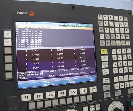
As it turned out, the opportunity to perform this test was valuable, because the capability did not work flawlessly when first used. Mr. Castor and Design & Software worked together to discover and fix what proved to be a flaw in the postprocessor that applied the PowerInspect data to the router’s Fagor CNC. Once that fix was made, the OSU pattern was modified accurately, and the Indiana company had unlocked a powerful tool for machining its free-from composite parts.
Simple Setup
Now, most of the machining of IndyCar-related CFRP parts is done on the router. While manual trimming and drilling is typical for composites manufacturing, CNC machining has come to be typical for Aerodine, and simplicity of setup is what made this possible, Mr. Castor says.
The steps of his setup of a CFRP part on the router now come down to this: He affixes the vise and fixture as described above (and perhaps the workpiece as well—read on). No measurements are made at this point, and no attempt is made to finely adjust their position. At the CNC, he has the router load the Renishaw spindle-mounted probe and he runs the probing routine for that part. In some cases the fixture is probed, and in some cases the part is probed (depending on the part number in question). Once this probing is done, he returns to his desk just outside the shop, where he applies the measurement data within PartAligner to discover the necessary rotation angles for the coordinate system to match the part’s orientation. He applies this new coordinate system to that part’s program within PowerMill and posts out a new program updated accordingly. Every workpiece thus gets its own uniquely posted program, fitted to that part’s location and orientation.
This entire process takes fewer than 10 minutes per part. The ease of setup is comparable to the time that was formerly required to mount a drilling and trimming jig back when these operations were manual.
And the gains the company has made by standardizing on this method of machining ultimately will extend beyond the motorsports industry, Mr. Castor says. The advance of the use of composites, particularly CFRP, is expanding the company’s opportunities. He sees this in the jobs coming into the shop. I got to see it, too; a job he was running on the day I visited involved parts for a well-known manufacturer of consumer products. This company (which knew of Aerodine because one of its engineers is an IndyCar fan) is contemplating a change to its processing lines that will replace aluminum components with components combining aluminum and CFRP. The challenge of these new components is that more than 100 holes have to be machined in each part at various precise compound angles.
Aerodine can meet that challenge with its router. And to set up for this precise machining, Mr. Castor doesn’t take precise measures—he just bolts each of that customer’s parts onto a block affixed to the table, without any attempt to square either the block or the part. Squaring to achieve precision would be superfluous, he notes. Probing to tailor the part’s program delivers better precision than any squaring effort he would be able to make.
Learn about Autodesk
Related Content
Ballbar Testing Benefits Low-Volume Manufacturing
Thanks to ballbar testing with a Renishaw QC20-W, the Autodesk Technology Centers now have more confidence in their machine tools.
Read MoreRethink Quality Control to Increase Productivity, Decrease Scrap
Verifying parts is essential to documenting quality, and there are a few best practices that can make the quality control process more efficient.
Read MoreTurning Fixed-Body Plug Gages Inside Out
Fixed-body mechanical plug gages provide fast, high-performance measurement for tight-tolerance holes.
Read MoreProcess Control — Leveraging Machine Shop Connectivity in Real Time
Renishaw Central, the company’s new end-to-end process control software, offers a new methodology for producing families of parts through actionable data.
Read MoreRead Next
Registration Now Open for the Precision Machining Technology Show (PMTS) 2025
The precision machining industry’s premier event returns to Cleveland, OH, April 1-3.
Read MoreSetting Up the Building Blocks for a Digital Factory
Woodward Inc. spent over a year developing an API to connect machines to its digital factory. Caron Engineering’s MiConnect has cut most of this process while also granting the shop greater access to machine information.
Read MoreBuilding Out a Foundation for Student Machinists
Autodesk and Haas have teamed up to produce an introductory course for students that covers the basics of CAD, CAM and CNC while providing them with a portfolio part.
Read More



.jpg;maxWidth=300;quality=90)


