One Setup Unrolls Six Linear Errors
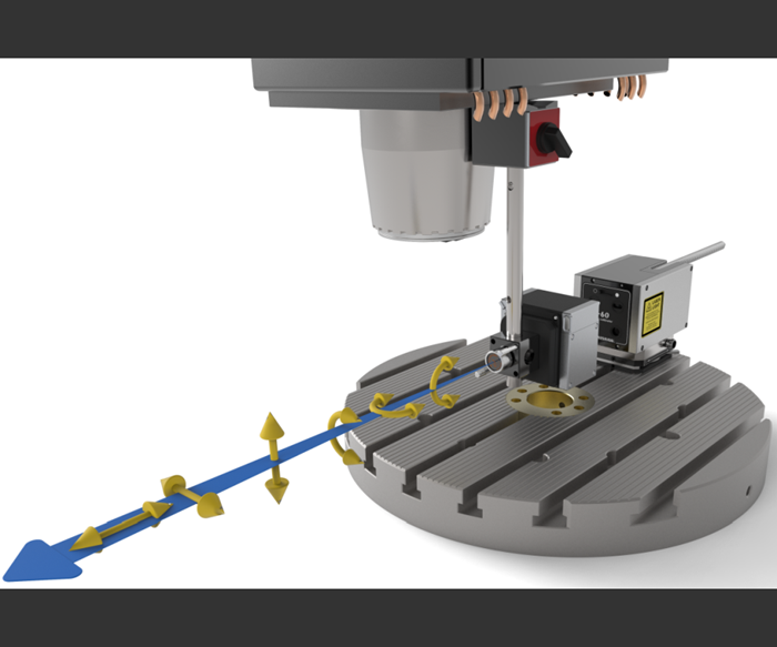
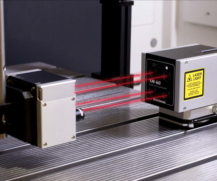
Consisting of only two components, this linear axis calibration device measures error in all six degrees of freedom—including roll—directly and in real time.
Share


The problem with calibrating linear axes on machine tools is that no error occurs in isolation. Linear displacement; vertical and horizontal straightness; roll, pitch and yaw—identifying just one as the culprit behind a misbehaving axis isn’t always easy. Michael Wilm, technical business director at Renishaw, says the most common methodologies unravel the complex interrelationships among the six degrees of freedom indirectly, whether through point clouds and sophisticated software algorithms or raw human labor and expertise.
Renishaw now offers another option: a system that not only measures every potential axis error directly—including roll, which Mr. Wilm calls “the holy grail”—but does so after a single, software-guided setup of only two primary components. That means no need to set up optics in multiple configurations, and no need for extensive expertise. What’s more, feedback is near instantaneous, both on the degree of each individual error and on how one error might be influencing another at any point along the axis. This capability reportedly enables manufacturers to quickly zero in on suspected axis errors and fix them, mechanically rather than via CNC compensation if need be, without any uncertainty and without waiting for data on the entire machine envelope.
Although traditional interferometric systems aren’t capable of directly measuring roll or of checking for all possible errors simultaneously, the XM-60 multi-axis calibrator heavily leverages the same technology. Interferometry is a measurement technique that extracts data from superimposed electromagnetic waves, in this case laser beams that are split in two and recombined. One beam reflects directly back from the opposing, axis-mounted optic, while the other is diverted along a different path first. The beams’ differing optical paths create an imperfect match between their identical wavelengths when they recombine. As the receiving optic moves down the axis, tracking the resulting changes in the pattern of this wavelength interference reveals the slightest difference in the lengths of the beams’ respective paths—and by extension, the slightest deviation in linear axis motion.
Checking for all six potential errors in a single linear axis requires multiple (split and recombined) beams and multiple optics. Consider checks for yaw and pitch, which indicate the extent to which the axis travel path tilts vertically or horizontally, respectively. Like other devices, the XM-60 checks for these errors with two parallel beams, oriented vertically for the pitch measurement and horizontally for yaw. Differences in the lengths of these parallel beams reveal the existence of an angle (and thus, a pitch/yaw error).
However, that’s where the XM-60’s similarities with traditional devices end, Mr. Wilm says. With all necessary optics contained in a single receiver unit and all necessary beams projecting from an opposing launch unit, yaw and pitch (and the other four degrees of freedom) can be calculated from a single set-up. A control-screen “target” grid helps make aligning launch unit beams with receiver optics fast and easy, he adds.
In contrast, moving between yaw and pitch measurements with a traditional interferometric system would require reorienting lasers and optics manually. Moving on to measure linear displacement or vertical or horizontal straightness would require setting up entirely different optics. All in all, it might take seven or more setups per axis to obtain a full picture of the linear axis error in a typical three-axis VMC, he says.
Even then, results aren’t always reliable because the three angular errors directly impact the three linear errors. Consider pitch or yaw. Due to the resulting angle in the axis slide, the presence of either error can distort a linear straightness measurement that targets an optic mounted too far off-center. “You have to shoot more than just linear displacement to see if your linear displacement reading is correct,” Mr. Wilm says.
Further complicating things is the fact that yaw and pitch get worse as the optic moves farther from where the error begins. Known as the pivot point, this is only the place along the axis’ travel where the angular error measures zero and thus cannot distort linear measurements, Mr. Wilm explains. The farther the travel from the pivot point, the greater the degree of angular error.
Faced with these realities, manufacturers usually strive to mount different optics for different measurements in the same location on the axis (a task that can be made difficult by machine tool structural elements). These locations are often chosen with the idea of using CNC offsets to ensure precision at a specific point in the workzone, whether at the center of the table or a “sweet spot” that’s specific to the machine, Mr. Wilm says. From there, personnel must calculate the precise extent to which one error affects another based on the degree of each error and the distance from the pivot point.
The XM-60 requires none of these mathematical gymnastics, Mr. Wilm says. The location of the pivot point ceases to matter, at least as far as the user is concerned, because all measurements are taken simultaneously from the same location along the axis. This provides instant feedback not only on the degree of each linear and angular error, but also on the extent to which the former affect the latter at any point along the axis’s travel.
Notably, this includes roll, an angular error, as well as the linear error measurements it can potentially distort: vertical and horizontal straightness. Although straightness can be determined via interferometry, roll has historically eluded this technique. So, the XM-60 doesn’t use interferometry at all to measure roll and the two straightness errors it affects. Rather than a laser, the unit’s fourth beam is dervied from a pair of high-intensity LEDs that are alternatively switched on and off.
Each beam is split by a prism within the receiver into two paths with opposite polarization. As the receiver rolls with respect to the incoming beam, the intensities of the two split beams vary in opposition. Measuring these intensity chagnes enables calculating absolute roll at any point along the axis to a resolution of 0.1 arcsecond, Mr. Wilm says. Meanwhile, a target within the receiver tracks the beam's location to reveal the sideways or vertical motions that indicate horizontal or vertical straightness error. He adds that the system is able to compensate and adjust for ambient lighting changes and alert operators to any potential inaccuracies as it measures.
Such peace of mind is critical when it matters—when a ballbar test or even an error reveals something wrong. In that case, manufacturing efficiency may depend on quickly identifying a problem and either fixing it or moving the work to a more precise area of the table, Mr. Wilm concludes. The XM60 is designed to make that easy.
Related Content
Parts and Programs: Setup for Success
Tips for program and work setups that can simplify adjustments and troubleshooting.
Read MoreProcess Control — Leveraging Machine Shop Connectivity in Real Time
Renishaw Central, the company’s new end-to-end process control software, offers a new methodology for producing families of parts through actionable data.
Read MoreHelp Operators Understand Sizing Adjustments
Even when CNCs are equipped with automatic post-process gaging systems, there are always a few important adjustments that must be done manually. Don’t take operators understanding these adjustments for granted.
Read MoreOrthopedic Event Discusses Manufacturing Strategies
At the seminar, representatives from multiple companies discussed strategies for making orthopedic devices accurately and efficiently.
Read MoreRead Next
Registration Now Open for the Precision Machining Technology Show (PMTS) 2025
The precision machining industry’s premier event returns to Cleveland, OH, April 1-3.
Read More5 Rules of Thumb for Buying CNC Machine Tools
Use these tips to carefully plan your machine tool purchases and to avoid regretting your decision later.
Read MoreSetting Up the Building Blocks for a Digital Factory
Woodward Inc. spent over a year developing an API to connect machines to its digital factory. Caron Engineering’s MiConnect has cut most of this process while also granting the shop greater access to machine information.
Read More


