Adjusting Feed Rate in Circular Motion Commands with G-Codes
While it is possible to calculate by hand adjustments to feed rate for circular milling operations, cutter radius compensation CNC programs streamline this process.
Share


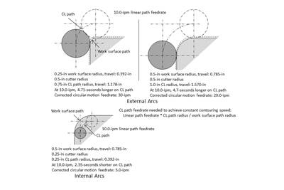
Previously, this column discussed an issue related to the feed rate required to make circular motions when targeting a constant contouring speed — specifically, with internal arcs or external arcs when removed material is balanced around a contour being machined (finish milling and near-net-shapes, for instance). The size difference between a milling cutter’s centerline path and the worksurface path requires increasing the linear motion feed rate for external circular moves and decreasing it for internal circular moves to achieve a constant contouring speed.
I demonstrated a method for determining the required modified feed rate for circular motions last month. But manually doing the related calculations is tedious, especially when using this technique regularly or for a variety of worksurface radius sizes. As long as one uses cutter radius compensation, and as long as the programmed coordinates reflect the worksurface path, the operator can enter the milling cutter’s radius size in a cutter radius compensation offset register.
When using right-hand milling cutters, the state of cutter radius compensation (G41-tool left, G42-tool right) helps determine whether a given circular command is machining an internal or external radius. Any G02 (clockwise arc) when the cutter is on the left side of machined surfaces (G41) will be an external arc. Any G03 (counterclockwise) will be an internal arc. The reverse is true when the cutter is on the right side of machined surfaces (G42). With FANUC Custom Macro, a program can access the cutter radius value from its offset register and access the current state of cutter radius compensation (G41 or G42).
I have created two user-defined G-code custom macros that make circular motions with the adjusted feed rate, naming them G102 (for clockwise) and G103 (for counterclockwise). I programmed them in the same manner as G02 and G03 (though they will not be modal). Each will compare the worksurface radius (specified by the R-word in the G102 or G103 command) with the cutter’s centerline path radius (calculated using the cutter radius from the offset register and the worksurface radius). They will then calculate the modified feed rate based upon the method shown previously and make the circular command using G02 and G03 with the modified feed rate.
What are the user-defined G-code programs?
Here are the two user-defined G-code programs:
- O9010 (G102, clockwise arc program)
- #1=#4109 (Retain current F-word)
- IF[#9NE#0]THEN#1=#9 (Test if new feed rate)
- IF[#9EQ#0]THEN #9=#1 (If no new feed rate, retain current feed rate)
- #2=[#_OFSDG[#4107]] (Access offset value)
- IF[#4007EQ41]GOTO5 (G41 condition, external arc)
- IF[#4007EQ42]GOTO10 (G42 condition, internal arc)
- #3000=100 (CRC COMP MUST BE USED)
- N5 (External)
- #3=#9*[#18+#2]/#18 (External feed rate)
- GOTO75
- N10 (Internal)
- #3=#9*[#18-#2]/#18 (Internal feed rate)
- N75G02X#24Y#25R#18F#3
- F#1
- M99
- O9011 (G103, counter-clockwise arc program)
- #1=#4109 (Retain current F-word)
- IF[#9NE#0]THEN#1=#9
- IF[#9EQ#0]THEN #9=#1
- #2=[#_OFSDG[#4107]]
- IF[#4007EQ41]GOTO5
- IF[#4007EQ42]GOTO10
- #3000=100 (CRC COMP MUST BE USED)
- N5 (Internal arc)
- #3=#9*[#18-#2]/#18 (External feed rate)
- GOTO75
- N10 (External arc)
- #3=#9*[#2+#18]/#18 (Internal feed rate)
- N75G03X#24Y#25R#18F#3
- F#1
- M99
To make these programs work as user-defined G codes, change two FANUC parameters (with current FANUC CNCs, they are parameters 6051 and 6052 for our example). After setting parameter 6051 to a value of 102 and 6052 to a value of 103, the CNC will execute program O9010 whenever it sees G102 and program O9011 whenever it sees G103.
Here is an example program that may be used for testing purposes. It is also a custom macro program, so the related variables may be easily modified. Prior to running this program, one must also set the value in the cutter radius compensation geometry offset (D register for offset 1 for this example) to the milling cutter’s radius.
By the way, if the cutter radius compensation offset register value is set to zero, the machine will use the work surface path. The cycle time will then come out nearly the same as when a value for the cutter radius is entered in the offset. The only time distance is related to the length of the motion is during the instating command for cutter radius compensation. This confirms that constant contouring speed is working as it should.
- O0041
- (G41 / G102, External arcs)
- #100=0.25 (Corner radius)
- #101=10.0 (feed rate)
- #102=1.5 (X length)
- #103=1.5 (Y length)
- T01M06
- G40G00X-1.5Y-.5
- G43H01Z-0.5
- G01G41D01X0F10.0
- G01Y[#103-#100]F#101
- G102X#100Y#103R#100
- G01X[#102-#100]
- G102X#102Y[#103-#100]R#100
- G01Y#100
- G102X[#102-#100]Y0R#100
- G01X#100
- G102X0Y#100R#100
- G00G40X-1.5Y-0.8
- M30
Notice that G102 is programmed just like G02: with X, Y and R. Local variables #24 (X), #25 (Y) and #18 (R) will be set accordingly. It calls program O9010, which will:
- Set local variable #1 to the currently active feed rate (so it can be reset after the circular move)
- If a feed rate is specified in the G102 command, set #1 accordingly
- Ensure that the feed rate (if included in G102) is retained
- Store the current cutter radius compensation offset value in local variable #2
- Execute from line N5 if a G41 condition exists (external arc)
- Execute from line N10 if a G42 condition exists (internal arc)
- Generate an alarm if cutter radius compensation is not currently instated
- Calculate the external arc’s feed rate if applicable
- Calculate the internal arc’s feed rate if applicable
- Make the circular command using G02
- Reset the feed rate to what it was prior to the circular motion
Nearly identical techniques are used with program O9011.
Related Content
Can Connecting ERP to Machine Tool Monitoring Address the Workforce Challenge?
It can if RFID tags are added. Here is how this startup sees a local Internet of Things aiding CNC machine shops.
Read More6 Machine Shop Essentials to Stay Competitive
If you want to streamline production and be competitive in the industry, you will need far more than a standard three-axis CNC mill or two-axis CNC lathe and a few measuring tools.
Read MoreFive-Axis Machines Speed NASCAR Engine Production
Moving from an aging set of five-axis mills to more advanced machines enabled Hendrick Motorsports to dramatically improve its engine production.
Read More5 Reasons Why You Should Know How to Write Custom Macros
Custom macros enhance what can be done in G-code programs, giving users the ability to code operations that were previously not possible.
Read MoreRead Next
T Codes Simplify Tool Length Confirmation Process
CNC users can program custom macros and T codes to ensure cutting tools are the proper length for tool length compensation in machining centers.
Read MoreHow to Modify Feed Rate for Circular Motion Commands
Maintaining a constant feed rate between linear and circular milling easily leads to chatter — for most applications, increase feed rate on external arcs and decrease it for internal.
Read More5 Common Mistakes When Using CNC Machines
Spend enough time on the shop floor and you will see some of the same mistakes time and again.
Read More
.jpg;width=70;height=70;mode=crop)


.jpg;maxWidth=300;quality=90)


