Understanding NURBS Interpolation
The right way to program curves? A solution to yesterday's problems? The truth is probably somewhere in between.
Share


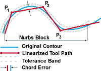
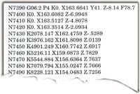
Non-Uniform Rational B-Splines—NURBS—have been used by CAD systems for some time. That's why it seems so natural that CNCs should be able to employ tool paths that are also defined in terms of NURBS. However, most CNCs today instead require contoured tool paths to be defined using straight lines, or chords. And this long-practiced approach can lead to inefficiencies familiar to almost any die or mold shop. Using chords to define complex geometries accurately results in large, data-dense program files—files that historically have been difficult to manage and slow to execute. The development of NURBS-interpolating CNCs promised programs that could define the same complex geometries with fewer blocks of code, and thus could provide some relief for the data-flow bottlenecks.
But something happened along the way. CNCs became more powerful, and powerful CNCs became less costly. Compared to the best controls available only a short time ago, many new controls today offer superior networking capability, cheap memory and faster processing speed. These improvements mean enormous program files for complex workpieces are easier to deliver to the CNC, where they can be stored entirely instead of drip-fed. And once there, the programs can be executed more efficiently. Processing rates on the order of 1,000 blocks per second, combined with CNC look-ahead features to smooth out inertial effects, can let a new control today execute even a long series of very tiny chords fast enough to keep a machine moving accurately at a high feed rate.
In short, the evolution of CNC technology has made some of the arguments for NURBS interpolation a lot less compelling today.
However, not all of NURBS inter-polation's benefits relate to program execution. In many cases where comparable programs defined through both chords and NURBS are run through a high speed control capable of executing either program effectively, the NURBS program allows the machine to realize a higher average feed rate.
So while some dismiss the benefits of NURBS interpolation—pointing out that it's now possible to machine fast and accurate contours with chords, too—others say NURBS can deliver efficiency gains to complex milling routines even where program execution is not a limiting factor. Is there a conflict between these two positions?
Not really. There is room for both proponents and skeptics of NURBS interpolation to be correct. And understanding why this is so can help you determine whether or not a NURBS-capable control merits a place in your shop.
What We're Talking About
Nurbs (Let's dispense with the capital letters from here on) are mathematical entities that allow a complex contour to be defined using only a handful of numbers. To understand this, imagine the way a circular arc can be defined using only a handful of numbers. If you know the coordinates of the start point, end point, and center of the arc, then you have all the information you need to reproduce that arc precisely.
Nurbs accomplish something similar, albeit for curves that can also be non-circular. In nurbs tool paths, data relate to the locations and "weights" of control points, each of which exercises a "pull" to give the curve its trajectory.
In fact, the comparison to a circular arc is useful indeed, because circular interpolation is another way CNCs can employ tool paths that are not straight lines. When the CNC executes a circular interpolation block, the feed rates of individual axes are not constants. Instead, they vary continuously throughout the move, so the resulting path of the tool tip traces some portion of a circle. In this way, a single program block can convey all the information necessary for the move. By contrast, using chords to define even a fair representation of some circular arc—a quarter of a circle, for example—would demand several program blocks in sequence.
Nurbs interpolation accomplishes something similar. The feed rate of each individual axis also varies continuously throughout a nurbs block, so the precise coordination between these varying axes results in tool tip motion that follows the intended curve. However, where circular interpolation is generally limited to two-axis moves, nurbs interpolation can govern three axes or more. And, of course, nurbs interpolation is not limited to circular moves.
NURBS And Speed
Nurbs interpolation consolidates the information that would otherwise be expressed through several chords into one block of code. Rules of thumb from multiple control makers say that a typical nurbs block can replace five to ten blocks of straight-line moves. And probably anyone with experience machining complex die or mold forms can recognize the potential benefit: Reducing the number of blocks reduces the risk of data starvation. That is, there is less danger of dwelling or chattering as a result of the machine axes outracing the CNC's ability to send them commands—either because processing speed is limited or because the CNC's limited memory means the program has to be drip fed across a slow network connection while the machine is in-cut.
Upgrading to nurbs interpolation can indeed address these data starvation problems. However, upgrading to a faster control can, too. So does this leave a place for nurbs interpolation?
Without a doubt, yes, says Bill Griffith, a CNC product manager with GE Fanuc (Charlottesville, Virginia) and the source for some of the information in this article. He points out that even newer controls are still prone to feed rate limits based on program processing speed during the most precise complex machining. And for controls that do face these limits, a reduction in program size translates directly to a higher available feed rate.
Granted, the file size savings from nurbs may not be as profound as the reduction in blocks would suggest. A nurbs program may use significantly fewer blocks than chords would require without using significantly fewer characters. That said, any given series of contouring moves defined through nurbs generally does require fewer data than the same moves defined through chords, and the difference can translate to a difference in productivity.
But the file size reduction is not the only source of potentially more productivity from nurbs, says Mr. Griffith. More compelling, he says, are the feed rate improvements that have nothing to do with processing speed.
He was as surprised to encounter these as anyone. Early in the development of nurbs interpolation, he watched as a chord program and a nurbs program, both based on the same geometry, were run by the same high speed control. The control had the processing power to execute both programs effectively. "That's why I had to scratch my head when the nurbs program still ran in less time," Mr. Griffith says.
The explanation was to be found in the economy of motion that nurbs interpolation makes possible. Compared to nurbs tool paths, chord tool paths leave the machine to accelerate and decelerate less efficiently, and this inefficiency alone can compromise cycle time.
To understand this, contrast a contour defined by a single nurbs block with the same contour defined by a series of straight chords. In the nurbs version, the feed rate of each axis changes continually and gradually all along the curve. But in the chord version, the feed rate of each individual axis is constant throughout each chord—until it reaches the end of that chord. At this point, the CNC commands a new feed rate for the axis, appropriate to the next line of code. In essence, the chord program asks the axes to change their feed rates instantaneously at the end of each block of code. Neither the axes nor the CNC can do this, of course, so the acceleration or deceleration to transition from one chord to the next introduces a cycle time delay.
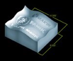
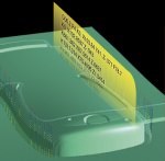
This is not to say that similar motion constraints don't limit the feed rate of a nurbs path; they do. However, the constraints are less constraining where feed rate changes are implemented more gradually. The result is reduced cycle times for parts machined using nurbs, as comparison tests have illustrated (see "NURBS Interpolation Test Part").
NURBS And Accuracy
Even if the ways in which nurbs can result in a higher feed rate are not immediately clear, it does seem intuitively apparent that nurbs interpolation should result in a more accurate part. After all, if the CAD geometry is defined in terms of nurbs, then tool paths that are also defined in nurbs should produce a part that more accurately reflects the CAD original. True?
In fact, no. It's not that simple.
Miles Arnone, president of Boston Digital (Milford, Massachusetts), included an analysis of nurbs interpolation in a recent book, "High Performance Machining" (from Hanser-Gardner Publications, a sister company to this magazine's publisher). Much of the information to follow draws on points he made there.
First, there is the question of how much accuracy is enough. No shop aims to achieve a "perfect" representation of the CAD model. Instead, a shop searches for an effective way to meet the specifications its customers require. So in comparing the accuracy of nurbs interpolation versus chords, the meaningful question is Which one will hold my tolerances?
And the answer is, they both will. There is no level of accuracy that nurbs interpolation can achieve that chord interpolation cannot also achieve. With the latter approach, obtaining a more precise representation of the original geometry is a matter of specifying a tighter chordal tolerance in the CAM software. This will result in shorter and more numerous chords, which in turn may cause the program length and file size to swell. Very precise files may be large indeed! The question then becomes whether or not the control can execute such a large program effectively. But again, CNCs today have become more adept at working with these large files.
In other words, nurbs interpolation can't deliver inherently better accuracy than chords. What it can do is deliver that accuracy in a more efficient format.
However, there is another, more practical aspect to the question of nurbs interpolation's accuracy. A nurbs tool path is not necessarily a direct expression of a nurbs-defined CAD model.
Using nurbs interpolation requires not just a CNC capable of it, but also a CAM system able to output nurbs tool paths. And these CAM systems can use a variety of approximations to get from one set of nurbs to the other. Here are just two reasons why:
- Surfaces are not tool paths. Mr. Arnone states it this way: "When a plane is intersected with a nurbs surface to create a tool path, a nurbs curve does not result." In other words, the software is still approximating to get to the tool path. And like any approximation, this one is governed by an accuracy band—comparable to chordal tolerance.
- A straight line may be the route between two curves. Some CAM systems translate the CAD geometry into nurbs toolpaths by generating a series of chords first, then translating the chord tool paths into nurbs. For CAM systems that use this approach, there literally is a chordal tolerance at work.
Finally, it's worth noting that at the level where the cutting tool hits the workpiece, the movement is still in straight lines. The CAD model may be represented by nurbs, the CNC may read tool paths in terms of nurbs, but when the CNC communicates movement commands to the processor controlling a given axis, it does this by specifying a target point. That is, a target toward which the axis advances in a straight line.
Granted, this straight line is very tiny. The CNC likely updates this target point more frequently than it processes program blocks—perhaps better than once every millisecond. In fact, the straight lines are so short, they can produce a cut that looks in every way as if the resulting tool path had followed a smooth curve.
But then, this further serves to illustrate the essential fact about the accuracy of nurbs versus chords: So long as the chords are short enough, they can deliver as much accuracy as any comparable nurbs program can deliver. It's just that you may pay a price in file size.
Summary
Take the following points away from this article:
- Nurbs interpolation offers an alternative to traditional chord interpolation for machining complex contoured forms, like dies or molds. If you are instead machining geometrically simple parts, nurbs interpolation can't help you.
- Nurbs interpolation may let you machine these complex forms at a higher average feed rate than you would achieve using chords, without compromising accuracy. CNC processing speed may provide the reason why, but there are other reasons, too.
- By itself, nurbs interpolation is not more accurate than chord interpolation. But when accuracy is required, nurbs can offer a more efficient way to achieve it.
Learning Curve
Straight lines offer the most natural way to define straight cuts. By contrast, nurbs offer a more natural way to define contoured cuts.
And according to GE Fanuc's Bill Griffith, this fact about nurbs—combined with the benefits these curves have shown they can deliver—will lead to nurbs interpolation's more widespread use.
But on the other hand, using chord interpolation for contoured cuts is another legitimate approach. And history predicts that this approach will continue to be used, Mr. Griffith says.
He draws another parallel to circular interpolation. This type of curve interpolation has been available for longer than a generation now. And circular interpolation is widely used; it's second nature to many shops. However, there are also many shops that don't take advantage of the capability, even when there is a clear application for it. And the reason they don't is simple. For these shops, programming the curves in terms of straight chords works just fine.
Related Content
Can AI Replace Programmers? Writers Face a Similar Question
The answer is the same in both cases. Artificial intelligence performs sophisticated tasks, but falls short of delivering on the fullness of what the work entails.
Read MoreHow this Job Shop Grew Capacity Without Expanding Footprint
This shop relies on digital solutions to grow their manufacturing business. With this approach, W.A. Pfeiffer has achieved seamless end-to-end connectivity, shorter lead times and increased throughput.
Read MoreOrthopedic Event Discusses Manufacturing Strategies
At the seminar, representatives from multiple companies discussed strategies for making orthopedic devices accurately and efficiently.
Read More5 Tips for Running a Profitable Aerospace Shop
Aerospace machining is a demanding and competitive sector of manufacturing, but this shop demonstrates five ways to find aerospace success.
Read MoreRead Next
Building Out a Foundation for Student Machinists
Autodesk and Haas have teamed up to produce an introductory course for students that covers the basics of CAD, CAM and CNC while providing them with a portfolio part.
Read More5 Rules of Thumb for Buying CNC Machine Tools
Use these tips to carefully plan your machine tool purchases and to avoid regretting your decision later.
Read MoreSetting Up the Building Blocks for a Digital Factory
Woodward Inc. spent over a year developing an API to connect machines to its digital factory. Caron Engineering’s MiConnect has cut most of this process while also granting the shop greater access to machine information.
Read More




.jpg;maxWidth=300;quality=90)


