
Breaking Chips and Controlling Burrs when Machining Automotive Transmission Components
Chip control is the bane of every shop’s existence and knowing how to consistently break chips and control burrs in ductile steels like SAE 1018, 1020, and 8620 is the holy grail of the tooling industry. When a shop experiences chip control issues, it affects their bottom line either through machine downtime, scrapped or reworked components, lost inventory due to broken tools or even employee injury.
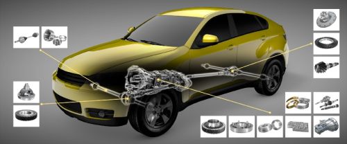
Many turning applications in the automotive transmission industry encounter chip control issues in semi-finishing, finishing and variable depth of cut operations.
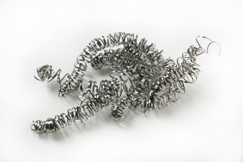
The long stringy chips produced when turning ductile steel can endanger operators, entangle cutting tools and damage the workpiece
Coolant pressures higher than 2,000 psi will be necessary to provide chip control effectively in typical automotive steels.
Share


Chip control issues are typically found in semi-finishing, finishing and variable depth of cut applications, which happen to be the vast majority of turning applications in the automotive transmission industry. This problem has probably frustrated carmakers going back to the days of Henry Ford and William C. Durant. Despite all of the technological advances in the automotive and tooling industries, machining these ductile materials still cause headaches for operators, engineers and production management. With the automotive industry experiencing and anticipating peak production levels, shops need to solve this problem to keep up with demand and stay profitable.
When it comes to solving chip control issues, physics and economics are not on our side. Everything we have been taught about efficient machining, including using tools with positive lead angles and using the largest nose radius possible, now work against us. While both of these solutions thin the chip, which increases tool life and productivity, they also make chip breaking that much more difficult. In addition to this problem, many components have Ra requirements that necessitate a large nose radius in order to achieve an acceptable surface finish.


The long stringy chips produced when turning ductile steel can wreak havoc on your operation and production. Chips that don’t break properly often wrap around tools causing downtime and frustrate operators who need to stop the machine frequently to manually detangle and evacuate the chips. Not only does this take time, but the edges of the chips are scorching hot and extremely sharp putting the operator at risk for injury. In addition, chips can drag along the parts, scoring them leading to scrapping or reworking components. More trouble ensues when long chips become trapped between the cutting edge and the component, resulting in tool breakage because the tool ends up “recutting” that chip.
In automated operations, cells with material-handling robots or inline gauging are also problems as chips can interfere with the performance of robots and give false readings on gauges.
Know Your Parameters
In a mass production environment, the components machined are castings or forgings. As a result, hogging off material is usually not an issue. Improving chip control in these operations comes down to four factors, the nose radius, the depth of cut, the feed rate and the top form geometry of the insert.
The goal is to maximize the chip area as much as possible while maintaining the accuracy of the component and upholding a productive cycle time. In order to increase the chip area, depths of cut less than the nose radius should not be taken. When a depth of cut is 0.010 inch per side with an insert that has a 0.031-inch nose radius, it thins the chip by about 60 percent making much more difficult to break.
The old school rule of thumb is that the depth of cut per side should never be less than 66 percent of the nose radius because, at that point, all chip thinning (which is a function of the size of the nose radius and depth of cut) stops. To maximize the feed rate to increase the chip area, the spindle speed needs to be adjusted accordingly. By far, spindle speed is the cutting parameter that most influences tool life. Depth of cut and feed rate also matter but have much less of an impact.
Of course, the other rule of thumb is that higher feed rates will sacrifice your surface finish. This is where wipers are best applied. When they were first introduced, wiper inserts were only used as a way to improve the surface finish. However, we now realize that these inserts can also increase productivity by increasing the feed rate while maintaining (and in many cases improving) the surface finish.
Make Use of Insert Technology
Most turning inserts today have a geometry pressed into the rake face to control chips. With literally hundreds of geometries available, shops can choose the best geometries to tackle different applications and component materials. When it comes to working with ductile steel, these materials require inserts with some very specific characteristics to form proper chips.
In most cases, the edge line or primary land should be narrow. For one-pass machining where we experience variable depths of cut, it is common to use geometries with lands that vary from 0.004 inch to 0.010 inch. The key here is to make sure your feed rate exceeds the width of the land. When your feed rate exceeds the width of the land it makes use of the rake angle and chip-forming ability of the insert geometry. The rake angle shears the material rather than the land to rub off the material. When machining with a feed rate that is smaller than the land width, heat is developed and has a negative effect on tool life. Optimizing your feed rate and land width also makes use of the chip-forming ability of the geometry. The various angles and “bumps” that make up the geometry are designed to drive the chip into obstructions that can mechanically break the chip. For lower feed applications, these chip formers, or bumps, need to be close to the edge line, especially at the insert nose radius.
The hardest chip breaking, which creates the shortest chips, occurs just above the nose radius for the cutting depth. So, adjusting the cutting depth and the nose radius is essential to optimize the cut. Using a smaller nose radius than usual, with a wiper, can be a successful, though less conventional, method.
And in some instances, like in the case of extremely tough material, it may be advantageous to break the chip against the primary land. Using a negative angle on the primary land essentially creates a “back wall” out of the chip former on the edge line, which in these unique circumstances, can be the only way to control the chip.
Program For Success
Whether we are trying to break a chip or our tool is “throwing a burr,” proper programming can make all the difference. A simple example is the common tool path of an OD turn with an out face. When we out face (face a shoulder by pulling away from the center line of the part) with a CNMG insert, the lead angle is 85 degrees. This is bigger than a lead angle typically seen on a high feed milling cutter which is usually 75 to 80 degrees. The premise of a high feed milling cutter is to thin the chip out as much as possible in order to increase productivity by using a feed rate of 0.040 to 0.060 inch per tooth. When the insert is faced out, a long ribbon-like chip is formed. Instead, a better technique is to in face or face from the OS to the center line of the part. By doing so we are making use of the negative 5-degree lead angle and maximizing our chip thickness.
Profiling cuts and forming radii are yet another challenge in machining ductile materials. In many cases, we can set our machine parameters correctly and choose the correct turning geometry to the point where we can achieve good chip breaking in OD and facing cuts. But in profile cuts, these same parameters and same geometry can produce an uncontrolled chip. In cases like this, it is sometimes beneficial to machine certain sections of the feature first. For example, when turning internal radii, plunging the radius in certain spots to make the chip break will eventually come off the radius smaller.
Keep Your Cool
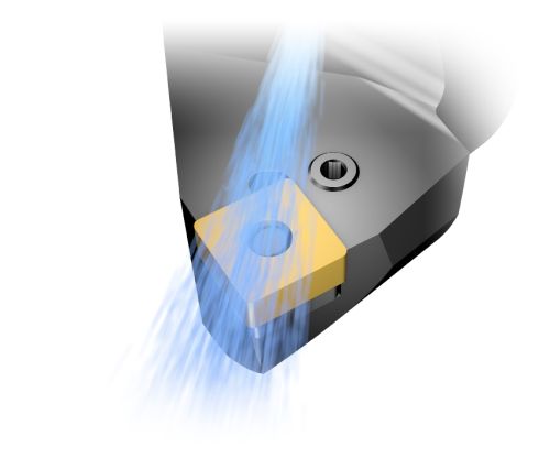
The advent of high-pressure coolant has made a considerable impact on chip control in ductile materials. Coolant streams at pressures of 1,000 psi can break titanium chips into what could be compared to a coarse powder. The same technology has been tested in typical automotive steels but without success and it has been determined that pressures of over 2,000 psi will be necessary to provide chip control effectively in these materials. Typically, high-pressure pump companies offer pumps that can provide 1,000 psi with a water based coolant and 2,000 psi for straight oil. However, in the near future we will see these companies offering higher-pressure pumps to deal with these problems.
Controlling chips and avoiding burrs is not a new problem when machining ductile steels. It’s a challenge that both tooling companies and shops have continuously worked to solve. Every so often, a new product is released that promises to be the cure-all, only to find its success limited to certain applications or that it solves only a small piece of the puzzle.
No shop wants to experience unnecessary downtime, waste time and money on scrap or reworking damaged components, throw away broken tools or risk their employee’s safety. Knowing how to handle these materials effectively by using proper cutting tool parameters, the latest insert geometries and high-pressure coolants to improve productivity and profitability will help shops keep up with increased demand for automotive transmission components now and in the coming years.


Related Content

Shoulder Milling Cuts Racing Part's Cycle Time By Over 50%
Pairing a shoulder mill with a five-axis machine has cut costs and cycle times for one of TTI Machine’s parts, enabling it to support a niche racing community.
Read More
How to Accelerate Robotic Deburring & Automated Material Removal
Pairing automation with air-driven motors that push cutting tool speeds up to 65,000 RPM with no duty cycle can dramatically improve throughput and improve finishing.
Read More
Custom Workholding Principles to Live By
Workholding solutions can take on infinite forms and all would be correct to some degree. Follow these tips to help optimize custom workholding solutions.
Read More
Fixturing Castings Made Simple Through Adhesive Workholding
When a casting proved too malleable for traditional gripping, Thomas/Euclid Industries adopted — and succeeded with — Blue Photon adhesive workholding.
Read MoreRead Next

Setting Up the Building Blocks for a Digital Factory
Woodward Inc. spent over a year developing an API to connect machines to its digital factory. Caron Engineering’s MiConnect has cut most of this process while also granting the shop greater access to machine information.
Read More
5 Rules of Thumb for Buying CNC Machine Tools
Use these tips to carefully plan your machine tool purchases and to avoid regretting your decision later.
Read More
Registration Now Open for the Precision Machining Technology Show (PMTS) 2025
The precision machining industry’s premier event returns to Cleveland, OH, April 1-3.
Read More