
Tips for Choosing Filter Settings When Measuring Round Shapes
When interpreting measurement data, the correct filter setting is necessary to see the difference between surface roughness and part roundness.

Share


ECi Software Solutions, Inc.
Featured Content
View More


Hwacheon Machinery America, Inc.
Featured Content
View More


Autodesk, Inc.
Featured Content
View More.png;maxWidth=45;format=webp)
DMG MORI - Cincinnati
Featured Content
View More


A probe arm mounted to a sensing transducer moves along an ideal circular or linear path to acquire data on the probe’s movements relative to this geometry. After completing the measurement, the system filters the data to determine the results. While this is an example of one of the most basic measurements to support a variety of manufacturing processes, users often perform some steps incorrectly. Errors are particularly common when choosing which filter value to use.
Using the Wrong Filter Values
Historically, the default filter value for roundness measurements has been 50 undulations per revolution (UPR). While this filter value may be suitable for many uses, it is not suitable for all. Luckily, new standards allow users to specify a filter setting directly in the drawing with any shape tolerance.


The correct choice of filter setting must be based on the measurement task. Engineering, manufacturing and quality management personnel are all responsible for defining requirement-related filter settings, recording the in-house standards and prescribing them for all internal and external suppliers. Filter selection has a significant influence on the quality of the measurement results.
Realistically, shape measurement is a process of measuring deviations. Traditionally, highly qualified specialists carried out the task in air-conditioned laboratories, but nowadays, it happens in the production environment where employees are often entrusted with a wide range of tasks.
Procedures for form and roughness measurements are essentially the same. In surface measurement, it is common to use many sample points to represent the entire surface. The user then filters these points to get only the data they want. For example, when examining surface roughness, the user retains the shorter-wavelength data for analysis, while discarding shape-related data because the information is not needed. In contrast, when measuring shape, the user filters out the short-wavelength data in order to measure the long-wavelength data representing the shape.
Shape-measurement filters can be confusing. For example, when discussing the measurement of surface roughness, the filter settings refer to millimeters or inches. When the filter is set to 0.8 mm, this is generally understood to mean that surface deviations of less than 0.8 mm are considered to be surface roughness, while elements larger than 0.8 mm are considered to be surface defects.
Shape filters for roundness measurements, however, are mostly specified as an angle size rather than length or distance. To make things even more confusing, the specifications are not given directly in degrees, but in a unit called “waves per revolution,” W/U or undulations per revolution. Many users choose 50 UPR as the typical standard value. This means that the length of the filter is 1/50 of a circle — 7.2 degrees.
Consider Workpiece Diameter for Filter Selection
A 50-UPR arc length, which corresponds to 7.2 degrees on the surface of a round object, changes with the diameter (d) of the object. A simple formula for the circumference of a cylinder is: π * d. So, a 4-mm-diameter cylinder would have a 12.57-mm circumference, and a 7.2 degree filter value would cut out an arc length that measures 0.25 mm along the surface. On the other hand, 20-mm-diameter cylinder would have a 62.83-mm circumference, and the 7.2 degree filter value would correspond to an arc length of 1.26 mm.
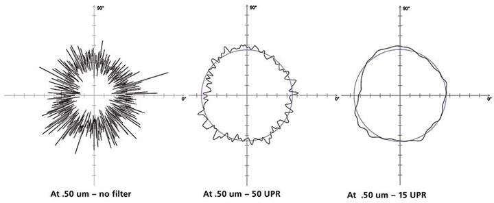
Figure 1: The selection of the filter has a significant influence on the quality of the measurement results. Photo Credit: Mahr Inc.
If the user maintains the same 50-UPR filter setting on the measuring device for both cylinders, then the larger part will qualify surface deviations five times as large as examples of surface roughness rather than defects.
The opposite is also sometimes the case: If measurement technicians do not understand that the filter setting has a significant influence on what is filtered out of the data or retained for the analysis, they may be tempted to choose a different setting. A different value will change the results and lead to one that “looks better,” but is not necessarily correct for the size of the test item. The bottom line is that users must set filters correctly for particular targets.


Related Content

Orthopedic Event Discusses Manufacturing Strategies
At the seminar, representatives from multiple companies discussed strategies for making orthopedic devices accurately and efficiently.
Read More
The Link Between CNC Process Control and Powertrain Warranties
Ever since inventing the touch-trigger probe in 1972, Sir David McMurtry and his company Renishaw have been focused on achieving process control over its own manufacturing operations. That journey has had sweeping consequences for manufacturing at large.
Read More
Parts and Programs: Setup for Success
Tips for program and work setups that can simplify adjustments and troubleshooting.
Read More
Process Control — Leveraging Machine Shop Connectivity in Real Time
Renishaw Central, the company’s new end-to-end process control software, offers a new methodology for producing families of parts through actionable data.
Read MoreRead Next

Registration Now Open for the Precision Machining Technology Show (PMTS) 2025
The precision machining industry’s premier event returns to Cleveland, OH, April 1-3.
Read More
5 Rules of Thumb for Buying CNC Machine Tools
Use these tips to carefully plan your machine tool purchases and to avoid regretting your decision later.
Read More
Building Out a Foundation for Student Machinists
Autodesk and Haas have teamed up to produce an introductory course for students that covers the basics of CAD, CAM and CNC while providing them with a portfolio part.
Read More