Thinking Outside The Cut
A Silicon Valley manufacturer's survival strategy involves closer relationships with customers, and high speed machining is crucial to this. The shop pays particular attention to the process factors that affect high speed machining before the cut takes place.
Share


Hwacheon Machinery America, Inc.
Featured Content
View More


Takumi USA
Featured Content
View More
Manufacturers that used to be flush with work are now struggling, and the struggle is made even more difficult by the amount of manufacturing going to cheaper sources overseas.
That predicament of U.S. manufacturers in general is even more pronounced for the semiconductor industry associated with Silicon Valley. This is the sector served by FM Industries, a subsidiary of NGK in Fremont, California.
David Miller is FM Industries’ president. He says he sees those overseas manufacturers continuing to close any gap in technology. “About the only defense is to increase efficiency and productivity,” he says. For his company, that has meant not just acceleration but integration as well.
The company makes the guts, basically, for processing chambers used in semiconductor production. Assembly occurs in a clean room at the heart of the Fremont facility.
In response to declining demand for its product, the company searched for a way to increase its share of customers’ business. The company asked itself this question: What if FM Industries could be relied on to produce not just internal assemblies but completed chamber modules instead?
That change would simplify customer supply chains.
It would also expand FM Industries’ role as a source of vital technical expertise.
And the principal challenge, the company realized, lay not in the clean room but in the CNC machine shop.
Body Parts
That shop had to begin machining the bodies for these completed chambers.
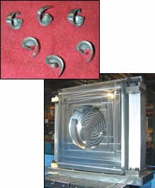
These parts, hogged out of solid aluminum, are not only elaborate but also large. A typical chamber body occupies a volume 30 inches square by 14 inches thick. It has a variety of complex details that vary significantly from one chamber design to the next. To become an outsource chamber manufacturer, FM Industries needed its shop to produce these challenging parts not just economically, but also within the tight lead times that are typical of the semiconductor supply chain.
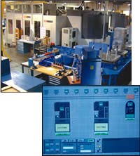
Step one was to get the right equipment. The company had no machines in house big enough to accommodate these parts. It purchased a Mazak Palletech cell including ten pallets and two CAT-50 taper, 50-hp machining centers capable of 15,000 rpm.
Step two was more difficult. The shop had to develop a process for using this equipment effectively.
When the first opportunity came to run a chamber body, the shop borrowed high speed machining techniques from its less powerful machines. The result failed to realize the new equipment’s potential, says engineering director Mark Filice. The customer’s deadline was met along with all of the other requirements, but it was clear to Mr. Filice and others that if the company would succeed as a chamber supplier, it was going to have to make chamber bodies in a fraction of the time this first part had required.
Part of what the shop learned is that a 50-taper machine may call for high speed machining techniques all its own. That insight sent the company down a path of fundamentally revising the process to achieve more efficient production. Kurt Sanfilippo, a recent hire for the company, joined this effort after it had already succeeded in cutting machining times in half. Now the Mazak cell manager, Mr. Sanfilippo is applying some 50-taper expertise of his own to put in place additional process improvements that are expected to remove two thirds of the processing time that still remains.
Much of this process engineering takes place outside the cut, he points out.
And within the cut, he says, the optimum machining is likely to occur below the top spindle speed. This is one potentially striking difference between higher-power and lower-power machines.
Speed Versus Volume
More important than the cutting speed is the metal removal rate. This is where Mr. Sanfilippo places his attention.
On a 40-taper machine, the most productive cutting is more likely to occur at the top rpm, he says. But on a 50-taper machine, particularly one with 50 hp, the highest metal removal rate may occur instead at a point along the power curve where horsepower remains high. While the shop generally does use the top rpm for finishing with 1-inch tools, the shop is more likely to run at 10,000 rpm when roughing or using larger tools. The lower speed lets the shop take advantage of much more spindle horsepower. Through strategic choices of tooling and tool paths during this high-power cutting, the shop is able to realize high feed rates that translate to a metal removal rate of 6 cubic inches per minute for every unit of spindle horsepower.
But removing so much material so quickly can place the quality of the part at risk. There is a danger of deformation as the material’s internal stresses are relieved. Therefore, rather than concentrate too much machining in one place during high-power cutting, the shop is careful to have the cutter leave the workpiece frequently so that it can skip around between far-removed features of the part. Often the tool moves back and forth between opposing faces.
To make the tool move from place to place in this way involves heavy-handed manipulation of the CAM software’s automatically generated tool paths. It also has implications for the way the work is held.
Workholding
Until now, chamber bodies have been held in place using tombstones. That is, they have been held the way that most parts in horizontal machining centers are held.
But tombstones limit the tool’s access, and therefore limited this shop’s ability to achieve aggressive metal removal. A tombstone makes it impossible for the tool to reach the “back” face of the part, even though the pallet can index in the B axis. The only two opposing faces the tool can reach in a single cycle are the two “side” faces, and in practice the tombstone’s clamping may obscure even these. Thus, the tombstones made it impossible for the shop to realize a milling strategy in which the tool moves frequently between regions located all the way around the part.
That’s why the shop is now moving toward a process in which parts are secured at the bottom, leaving four faces of the part freely available. The workholding that accomplishes this employs a special design that the company itself developed. The workholding will not only permit aggressive machining, but also will reduce the number of setups. What used to require ten operations now will require five. The number of committed pallets also decreases, from eight pallets per part to four.
And yet holding the part is not all that a tombstone does. It also locates the part precisely in three-dimension space. Clamping the part against the square face of the tombstone can ensure that the part is located squarely, for example. And for hog-outs such as the chamber bodies, clamping holes drilled into the regions of stock that will be machined away can make variations in the raw stock dimensions unimportant. How can the shop expect to realize the same precise location for a large part that simply rests on its bottom edge?
Mr. Sanfilippo says the answer comes from probing. Machining cycles for the chamber bodies include numerous probing routines. “The probe is our most important tool,” he says.
Probing
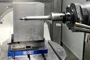
Use of the probe saves time by eliminating errors. The machine’s spindle-mounted Renishaw touch probe verifies that the right pallet has been loaded, the right workpiece is on the pallet, and the work has been positioned correctly. There are even frequent moves that serve only to verify that the probe itself is still measuring correctly.
Probing also reduces setup time because operators don’t have to be so exacting about the part’s location. Rather than require operators to minutely move and adjust the part to match some fixed coordinate system of the machining program, the CNC can shift this coordinate system to match the location of the workpiece as measured by the probe. If the part is located off-center compared to the axis of rotation of the pallet, the CNC can shift its coordinate system off-center by the same amount, compensating even for the trigonometric offsets created when the pallet turns. In fact, if the work itself is not aligned squarely, the CNC can add an angular offset in the B axis to compensate for this discrepancy.
Another step the shop can avoid through probing is pre-machining of the raw stock. Through probing, the CNC can measure how much stock is present and tailor the depth of cut or the number of machining passes accordingly.
Many shops would have difficulty seeing all of this probing take place. The machine is expensive; its time is expensive, so the common thinking is that the machine should be making chips. The relatively slow and quiet probing moves look a lot like unproductive time.
But the reduction in setup time makes these probing moves productive indeed. Thanks to probing, an operation that used to require 2.5 hours including the setup time was reduced to 1.5 hours. Then there is the reduction in machining error, which results in further savings still.
Probing also plays a direct role in FM Industries’ variety of high-metal-removal-rate cutting. After the machine has taken a particularly fast and heavy cut, did the workpiece shift position? Probing can check the answer to that question. This allows the shop to run much closer to the clamping force of its workholding, instead of restricting the process to cutting parameters that are too light and overly cautious.
All The Rest
Missing from this discussion are the tools used, the toolholding, the speeds and feed rates, the toolpath strategy—in short, all of the process components that shops routinely struggle with as they try to make high speed machining productive. FM Industries uses custom cutting tools and custom toolholders, so discussing these process details too specifically would risk divulging proprietary secrets. But at the same time, such a discussion would overlook the most significant way that FM Industries’ process is noteworthy compared to other successful high speed machining applications. Engineering the process to be effective in the cut is how most practitioners approach high speed machining. Working more effectively around the cut provides opportunities to improve the process even further, and these opportunities often go unexplored.
Related Content
Inside a CNC-Machined Gothic Monastery in Wyoming
An inside look into the Carmelite Monks of Wyoming, who are combining centuries-old Gothic architectural principles with modern CNC machining to build a monastery in the mountains of Wyoming.
Read MoreWhich Approach to Automation Fits Your CNC Machine Tool?
Choosing the right automation to pair with a CNC machine tool cell means weighing various factors, as this fabrication business has learned well.
Read MoreHigh RPM Spindles: 5 Advantages for 5-axis CNC Machines
Explore five crucial ways equipping 5-axis CNC machines with Air Turbine Spindles® can achieve the speeds necessary to overcome manufacturing challenges.
Read MoreBuilding Machines and Apprenticeships In-House: 5-Axis Live
Universal machines were the main draw of Grob’s 5-Axis Live — though the company’s apprenticeship and support proved equally impressive.
Read MoreRead Next
Building Out a Foundation for Student Machinists
Autodesk and Haas have teamed up to produce an introductory course for students that covers the basics of CAD, CAM and CNC while providing them with a portfolio part.
Read MoreRegistration Now Open for the Precision Machining Technology Show (PMTS) 2025
The precision machining industry’s premier event returns to Cleveland, OH, April 1-3.
Read More5 Rules of Thumb for Buying CNC Machine Tools
Use these tips to carefully plan your machine tool purchases and to avoid regretting your decision later.
Read More





.jpg;maxWidth=300;quality=90)


