
The Nuts and Bolts for Getting the Gaging Fixtures Right
Gage fixtures are the key to accurate and repeatable measurements, so make sure there is no play at its joints.

Share


Most comparative gages consist of three parts: an indicating device (a dial, digital indicator or comparator), a setting master to set the gage to the nominal dimension of the part and the actual gaging instrument itself.
Considering the high performance of today’s digital indicators and comparators — which sometimes approach the capabilities of a bench amplifier — and the documented control of measuring standards, it is tough to squeeze much more performance out of these two parts without spending more money. So, to ensure the best performance from the whole gaging station, one can get the best return by concentrating on the mechanical setup of the gaging fixture, which has the potential for the most common gaging errors.


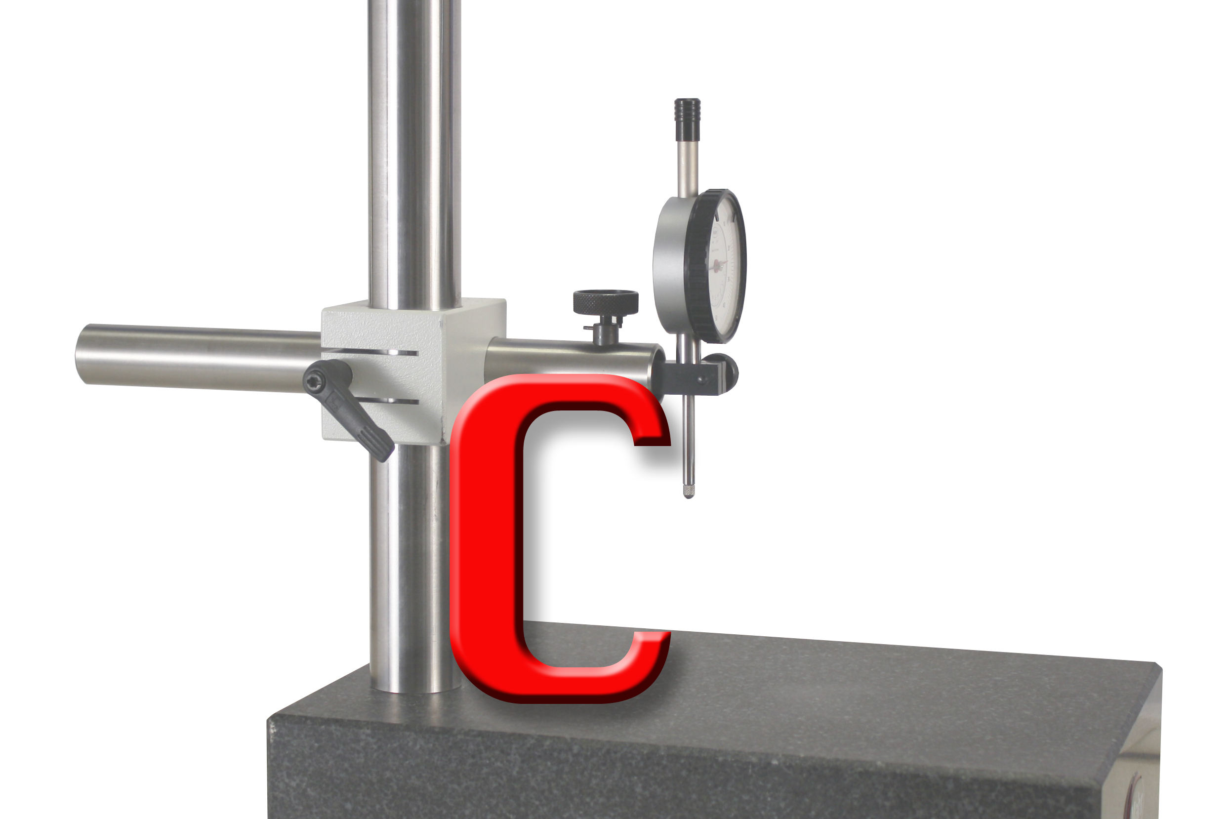
The mechanical gaging fixture establishes the relationship between the indicating device (a dial/digital indicator) and the workpiece, so any error in the fixture inevitably shows up in the measurements. Many fixtures are designed as a variation of a C-frame shape and, as such, have a substantial cantilever subject to deflection. This problem is greatly reduced if the fixture is a solid, one-piece design.
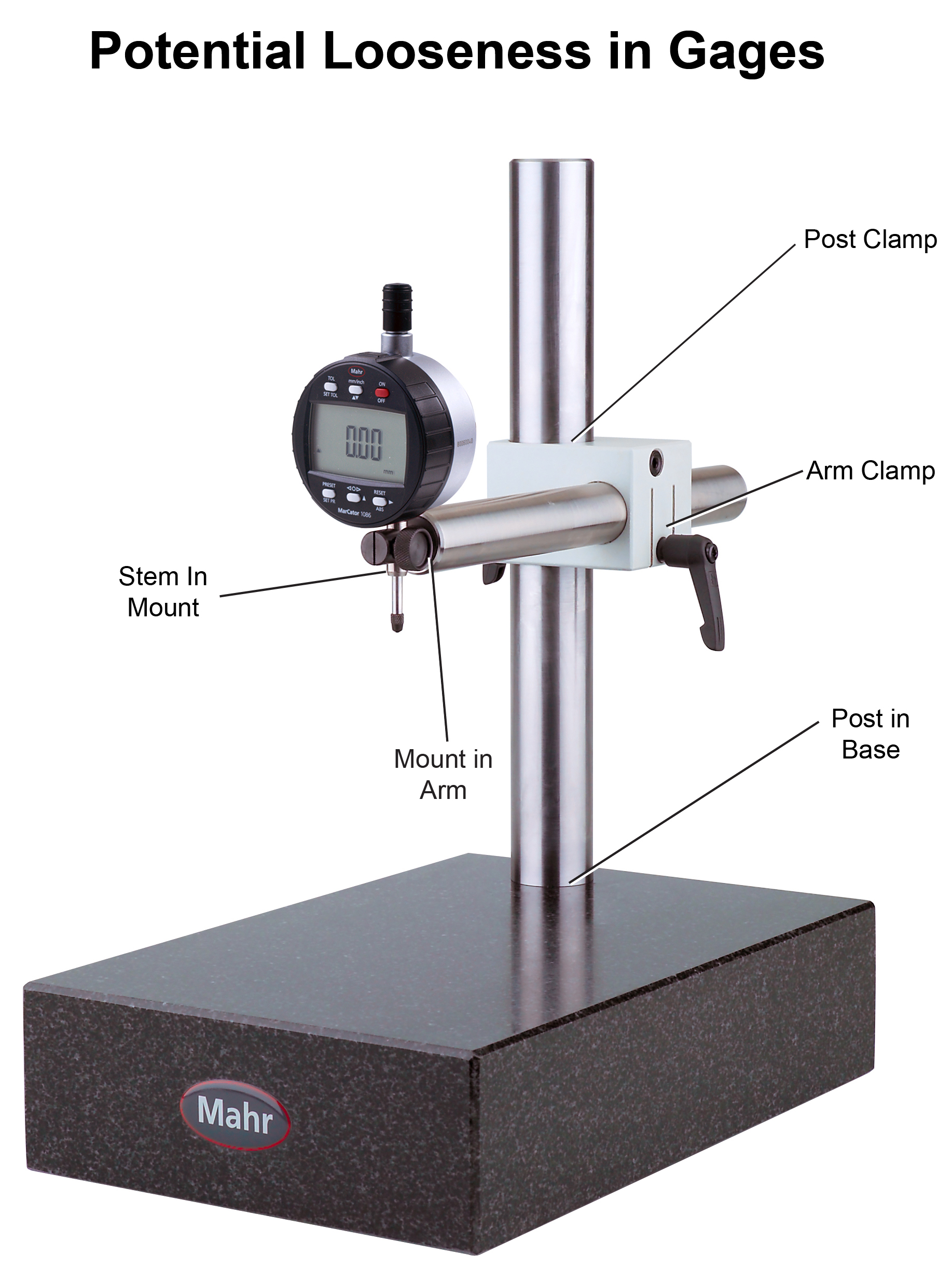
Generally, most fixtures tend to be universal, made for many different applications and adjusted to the task at hand. This is usually the universal bench stand, which typically consists of a minimum of three pieces: a base, a post and an arm. These components must be fastened together with absolutely no play between them.
As a rough rule of thumb, any movement between two components will be magnified at least tenfold at the workpiece. A little looseness of only a few millionths can, therefore, easily accumulate through a couple of joints so that measurements to ten thousandths become unreliable, which is easily visible on the high-resolution indicating device.
Tight tolerances are being called for on many parts — tighter than you can perceive by eye or touch. Looking at most gage fixtures today, the design of choice is to use a clamping split bushing type of locking mechanism to secure two gage components together.
In some designs, a set screw may be used to secure two parts together. However, no matter how tightly a single set screw is tightened, it often acts merely as a point around which components pivot. This is the reason why most comparator stands use the split clamp concept, providing more line contact between the components.
Lost motion due to play between fixture components is dangerous. There is a place on a gage, however, where a loose assembly may produce erratic readings, making the setup completely unreliable. Most dial or digital indicators offer interchangeable contact points designed to be changed by the user. Since the contact point is a wear item subject to checking thousands of parts and absorbing the start of the measurement, it is subject to a lot of force that may potentially loosen it over time, especially if it is not properly tightened when changed. Some indicators or linear variable differential transformer-type (LVDT) probes will be provided with a flat on the spindle, which is used with a wrench to hold the spindle while tightening the contact point. This is to secure a contact without applying too much force on the spindle.
In addition to ensuring that the fixture gage is locked into position to gage the part, one should also ensure the part is locked into position. Many gaging stands provide a large surface area, enabling one to measure a wide variety of parts of different shapes and sizes. This versatility, however, may cause what some could consider non-repeatable readings because the gage is not checking the same point of the part every time.
To reduce these part-influenced errors, accessory positioning devices may be used to increase the comparator’s repeatability in various applications. A flat backstop permits lateral exploration of the part for variation, while a vertical vee used as a backstop permits rotational exploration of round parts.
A vee can also be mounted horizontally, thus serving as a reference in two directions. Round workpieces may also be held horizontally between a pair of centers attached to the base for runout inspection. A second horizontal arm may be attached to the post to act as a backstop for the part to ensure all parts sit at the same gaging point. All these accessories ensure the part is secure, just like the locking devices on the stand.
Regardless of complexity, your gage fixture is the key to accurate and repeatable measurements. Make sure there is no play at its joints. Check that the instrument itself is assembled securely. And finally, confirm that the gage measures workpieces and masters at identical locations.


Related Content

How to Calibrate Gages and Certify Calibration Programs
Tips for establishing and maintaining a regular gage calibration program.
Read More
Orthopedic Event Discusses Manufacturing Strategies
At the seminar, representatives from multiple companies discussed strategies for making orthopedic devices accurately and efficiently.
Read More
The Link Between CNC Process Control and Powertrain Warranties
Ever since inventing the touch-trigger probe in 1972, Sir David McMurtry and his company Renishaw have been focused on achieving process control over its own manufacturing operations. That journey has had sweeping consequences for manufacturing at large.
Read More
Rethink Quality Control to Increase Productivity, Decrease Scrap
Verifying parts is essential to documenting quality, and there are a few best practices that can make the quality control process more efficient.
Read MoreRead Next

Setting Up the Building Blocks for a Digital Factory
Woodward Inc. spent over a year developing an API to connect machines to its digital factory. Caron Engineering’s MiConnect has cut most of this process while also granting the shop greater access to machine information.
Read More
Registration Now Open for the Precision Machining Technology Show (PMTS) 2025
The precision machining industry’s premier event returns to Cleveland, OH, April 1-3.
Read More
5 Rules of Thumb for Buying CNC Machine Tools
Use these tips to carefully plan your machine tool purchases and to avoid regretting your decision later.
Read More