Steering Clear Of Corner Concerns
Tool paths based on constant stepovers often get an end mill into trouble when it heads into a corner. Using the tool's angle of engagement as the constant avoids this difficulty.
Share


In the effort to make machining more productive, the industry has been addressing all of the factors that seem to limit material removal rates.
Machine tool builders and cutting tool manufacturers have designed and built hardware capable of removing more cubic inches per minute. Control units have been designed to handle huge amounts of data and drive ever more sophisticated machine tools faster and more accurately. Meanwhile, CAM software developers have devoted much attention to streamlining, even automating, the NC programming process.
Substantial progress has been made on all of these fronts, and further advancements are becoming available all the time. Yet some observers believe that these developments are now at the point of yielding only incremental improvements, and no breakthroughs appear to be on the horizon.
Glenn Coleman, vice president of product design at Surfware Inc. (Westlake Village, California) disagrees. He believes that an opportunity to boost milling productivity has been overlooked and that fundamental aspects of CAM software are a major limiting factor. The best evidence for this position, he says, is a new toolpath engine that the company has developed.
“The limiting factor in material removal rates is not the machine tools, the cutting tools or any other hardware component involved in the process,” Mr. Coleman says. “The limiting factor is the input to the machines, the very tool paths that drive them. Machines only do what they are told, and tool paths give the orders.”
Typical tool paths often drive cutting tools into corners where the machining load increases, requiring NC programmers to use reduced machining parameters. This means lowering spindle speeds, feed rates or depths-of-cut, reducing stepovers or some combination of these in order to preserve the cutting tool.
To break this barrier, developers at Surfware discarded fundamental concepts upon which existing tool paths are founded and rebuilt the tool paths based on a machining dynamic that they say has been neglected since the inception of numerical control.
Angle Of Engagement
According to Mr. Coleman, virtually all existing toolpath strategies are based, at least at the root level, on maintaining a constant stepover distance between cuts. This is a holdover from the days of crank handles and the infancy of numerical control—when the immediate goal was to automate manual machining methods. The results remain in effect today. “This is unfortunate, because maintaining a constant stepover ensures a non-constant load on the cutting tool. The non-constant load on the cutting tool is the factor that forces the use of reduced machining parameters,” he says.
When a cutting tool enters a corner, more of the tool becomes surrounded by, or engaged with, the workpiece material. This engaged portion of the tool can be measured and expressed as an angle, the tool engagement angle (TEA).
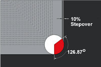
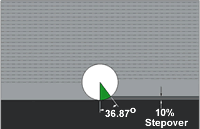
Some basic math shows why this angle is important. There is a geometrical relationship between a stepover value and a TEA. A stepover value of 50 percent of the cutter diameter results in 90 degrees of the periphery of the tool being engaged with the material, for example. A 10 percent stepover equates to a TEA of 36.87 degrees, for example. (See Figure 1.) For any given stepover value, there is only one corresponding TEA. However, this is true only when cutting along a straight line with a constant radial depth of cut. When the tool turns a corner, the TEA increases as a function of the angle or radius of that corner, as shown in Figure 2. This increase in TEA is what causes the tool load to increase.
“So, for all its history, basing toolpath strategies on maintaining a constant stepover between cuts doesn’t appear to follow the best logic,” Mr. Coleman concludes. The problem is that the variations in tool load that result subject the cutting tool to adverse conditions. Unless the operator or the control unit adjusts machining parameters to mitigate this situation, tool life suffers. Surface finish and other workpiece characteristics may also be affected negatively. However, when adjustments are made, cycle times are likely to increase.
Although a TEA cannot be held strictly constant, the company contends that it can be controlled to great advantage.
Based on this insight, the software design team started rethinking CAM software, including their Surfware’s own products, and how tool paths for milling were generated. Machinists and NC programmers by training, they looked at how managing the tool’s engagement with the workpiece material could be used in toolpath algorithms. These algorithms would have to be different from those normally applied in CAM software. New formulas for calculating tool paths needed to be developed and encoded.
“Designing a toolpath strategy to accomplish this was not trivial, and implementing the solution was even more difficult, but it has been done,” Mr. Coleman says. Raising the design concepts to the level of a functioning product required using mathematical tools and programming principles that the company believes have not been previously leveraged in CAM software development. The ultimate result of this effort is the TrueMill toolpath engine, which has been incorporated in the company’s SurfCAM Velocity product.
Paths That Fit To A TEA
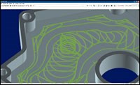
This software considers the user-defined stepover and the diameter of the cutting tool to determine the corresponding TEA, assuming a straight-line cut. The tool path is then generated so that this tool-engagement angle is never exceeded. “Because the tool paths are decidedly not based on a constant stepover, their motion is completely different from those that are,” Mr. Coleman says. “As such, they look foreign, even bizarre, to most first-time observers.” (The illustration on page 93 shows an example). However, he is quick to add that the way a tool path looks is not important; it is how it performs that matters.
By keeping the TEA below a known threshold, tool load also stays below a known threshold. This enables programmers to use recommended feeds and speeds as minimum parameters, which can be increased based on the capabilities of the machine tool and cutting tools in use. With existing technology, most programmers use recommended feeds and speeds as not-to-exceed thresholds and decrease them based on the limitations imposed by the tool path. This trade-off, however, sacrifices material removal rates.
The new toolpath engine is designed to avoid this trade-off. As a cutting tool moves through the material, it alters the material’s shape for the next cut. In order to control the engagement between the tool and material, this dynamically evolving material boundary has to be managed. According to the company, all tool motion is calculated so that the in-process material boundary for the next cut is precisely known. This means that the tool paths are calculated based on material removal requirements, rather than on the shape of the part geometry. “This approach also contributes to the strange appearance of the tool paths; they are not driven by the shape of the area being machined,” Mr. Coleman says. “That shape is ultimately established, of course, but it doesn’t become evident until the final passes of the tool.”
What Is Heard (Or Not) At The Machine
Because the tool’s engagement with the material is controlled, there is much less stress on the machine tool and cutting tool, compared to that resulting from tool paths generated by other methods. There are no chirps or squeaks in the corners because these tool paths literally have no corners. Often, the sound from the spindle motor or coolant pump is significantly louder than the sound of the metal being cut, Mr. Coleman reports. The TEA cannot be effectively managed if there are sharp corners in the tool path, so the software does not create them. The boundary geometry may contain sharp corners and be of any shape, yet all moves with the tool path remain smooth and tangential.
Nevertheless, the true measure of any tool path is how fast it removes material on the machine. Surfware claims that users are experiencing “heretofore unheard of productivity increases.” For example, one customer machining an aluminum mold insert for a proprietary aerospace component reports that this part was previously machined in slightly over 1 hour, but is now machined in less than 8 minutes with TrueMill. “The results are not mere percentage points faster; parts are being machined in a fraction of the time compared with previous tool paths,” Mr. Coleman says.
Software that manages the TEA is apparently proving especially effective in harder materials. According to Mr. Coleman, this is because the penalty for overloading a cutter is more severe in harder materials than in softer materials. Many of the newest cutting tools can survive being overloaded in softer materials such as aluminum, at least occasionally and for brief periods, he says. “The same cannot be said when machining tool steel, for example. In such materials, even a single instance of tool overload at too fast a feed rate can result in catastrophic tool failure.” Because managing the TEA avoids these overloads on a cutter, this cause of failure is not an issue.
Mr. Coleman offers other examples of successful applications. One site in the Midwest machined 4140 steel with a ½-inch diameter, solid carbide, four-flute end mill, at a 12,000 rpm spindle speed and a 1,000 ipm programmed feed rate. This was not accomplished by using light cuts. The axial depth of cut was ½ inch and the TEA was 64 degrees, which equates to a programmed stepover of 0.140 inch. A site in Germany milled a 64 Rockwell C material at 300 ipm with an 8-mm diameter cutter with 2-mm radius button inserts.
For Consistency’s Sake
One of the reported downsides of using tool paths based on constant stepover is inconsistency in tool performance. The consequences of variations in cutter conditions are difficult to predict, so they have to be monitored closely. Managing TEA, however, yields a higher degree of toolpath consistency, Mr. Coleman says, and this characteristic has elicited the most positive comments from users.
“Because there are no spikes in tool load, if a newly programmed path is running well for the first few seconds, chances are excellent that it will run well throughout. Operators can walk away from the machine without worrying about the unexpected; there is no need to hover over the feed override control,” he says.
Getting away from constant stepovers means stepping into some uncharted territory in machining, Mr. Coleman adds. “Because this is a new area, there are some unknowns,” he warns. Arguably the biggest of these is the shortage of appropriate machining data. The existing data is far too conservative, he says. He predicts that much will need to be learned through experimentation.
Surfware recommends running simple straight-line test cuts on the edge of a block so that the user can find machining parameters that provide the best combination of material removal rates and cutting tool life. The company suggests that users may be quite surprised at how fast they can cut under such ideal machining conditions. From then on, those parameters can be used with the same tool and with the same material regardless of the shape of the part.
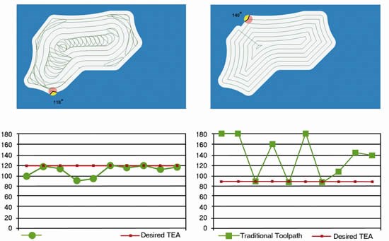
Also important is the fact that cutting tools tend to last significantly longer even though machining parameters are increased. Figure 3 shows the same pocket programmed with a TrueMill tool path and with a standard SurfCAM tool path. Because of the controlled tool load and automatic floor cleanup that the first tool path offers, it can be safely programmed at a larger stepover value than the standard path, as this test shows. At common points selected from the tool paths, the first tool path never exceeds its target TEA, whereas the standard path is almost always above its target. The standard path includes areas where the cutter is fully engaged. This illustrates that, even at more aggressive machining parameters, there is less stress on the cutting tool with the new tool path than with a path generated with existing technology. Reducing this stress extends tool life.
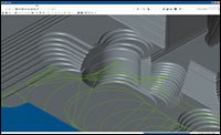
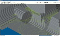
The developers of this software began to deliver it to end users with the release of SurfCAM Velocity in August of 2005. In that release, the technology is limited to 2 1/2 axis milling. The company plans to extend the concept to complex, multiple-surface rough milling functionality in the first quarter of 2006. Figure 4 on page 94 previews the results of this extension.
Related Content
Generating a Digital Twin in the CNC
New control technology captures critical data about a machining process and uses it to create a 3D graphical representation of the finished workpiece. This new type of digital twin helps relate machining results to machine performance, leading to better decisions on the shop floor.
Read MoreThe Power of Practical Demonstrations and Projects
Practical work has served Bridgerland Technical College both in preparing its current students for manufacturing jobs and in appealing to new generations of potential machinists.
Read MoreTips for Designing CNC Programs That Help Operators
The way a G-code program is formatted directly affects the productivity of the CNC people who use them. Design CNC programs that make CNC setup people and operators’ jobs easier.
Read More5 Tips for Running a Profitable Aerospace Shop
Aerospace machining is a demanding and competitive sector of manufacturing, but this shop demonstrates five ways to find aerospace success.
Read MoreRead Next
Building Out a Foundation for Student Machinists
Autodesk and Haas have teamed up to produce an introductory course for students that covers the basics of CAD, CAM and CNC while providing them with a portfolio part.
Read MoreSetting Up the Building Blocks for a Digital Factory
Woodward Inc. spent over a year developing an API to connect machines to its digital factory. Caron Engineering’s MiConnect has cut most of this process while also granting the shop greater access to machine information.
Read MoreRegistration Now Open for the Precision Machining Technology Show (PMTS) 2025
The precision machining industry’s premier event returns to Cleveland, OH, April 1-3.
Read More




.jpg;maxWidth=300;quality=90)


