Standardized Parameters Make Unattended Machining Reliable
Standardized parameters for specific material and cutting tool combinations help this hard milling specialist manage a highly varied workload with minimal labor.
Share


When Corey Greenwald arrives for work on any given morning, chances are good that all eight milling machines on the shop floor have already been running for at least an entire shift. In fact, it’s not uncommon at Hard Milling Solutions (HMS), the company he founded in 2004, for a machine to run without interruption for days. What’s more, HMS is in no way a production operation. In fact, a large portion of jobs at this 4,900-square-foot, Detroit-area shop are one-offs. “Our goal is to ensure that the only time machines are not running is when we’re setting them up or adding programs,” Mr. Greenwald says.
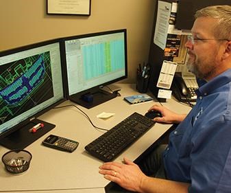
Keeping unsupervised spindles spinning is as much about mentality as process or technology, he claims. More specifically, the difference-maker for HMS has been a willingness to subordinate individual instincts to shop-wide best practices based on proven, historic machining performance. These best practices are codified in a CAM software database of the most effective speeds, feeds, stepovers and stepdowns for machining specific materials with specific, inventoried cutting tools. Standardizing on these parameters not only reduces work for programmers, but also ensures that they take full advantage of experience gained from countless past jobs—experience that now belongs to the organization as a whole, including fresh hires, rather than being locked up in the heads of specific individuals.
The more work the shop takes on, the more it refines these parameters, thus ensuring that lessons learned provide a potential foundation for even greater future efficiencies. Most recently, the shop has combined multiple database entries into templates that standardize and automate as much as 80 percent of the programming for certain parts. “The database and the templates say a lot about who we are as a company,” Mr. Greenwald says. “Our primary goal with this system is to ensure every programmer cuts the same way, and gets the same results. We want customer needs to dictate what comes out of this company, not the experience and ability of any one individual.”
Controlled Chaos
Mr. Greenwald says he had this system in mind ever since he founded HMS 12 years ago with a single machine tool: a Makino V56 that he says is still just as reliable as ever. Among other features, this machine’s rigidity; volumetric accuracy; and 20,000-rpm, internally cooled spindle would prove essential to filling the company’s chosen niche: precision milling of materials ranging into the 60s on the Rockwell hardness scale. Likewise, CAM software tool paths that keep chip load constant would be critical to meeting the demands of hard milling. However, Mr. Greenwald also chose CGS North America’s CAM-Tool system for another reason: the software’s support for a digital tool library. Although he says this feature wasn’t as common among CAM offerings at the time, he knew it would be essential for quickly populating part programs with geometrically defined cutting tool/toolholder assemblies and their associated parameters.
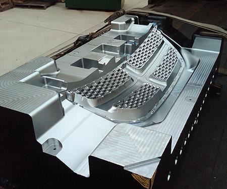
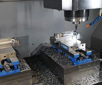
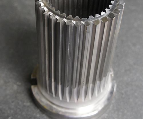
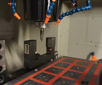
That capability, in turn, would help control the chaos of the high-mix work sourced largely from toolmakers, particularly plastic injection mold manufacturers seeking the capacity and/or the capability to limit labor-intensive polishing and spotting. As capacity expanded, so did the shop’s customer base, making the challenge even greater and the expanding treasure trove of best-practice parameters even more important, Mr. Greenwald says. Today, HMS is home to seven Makino VMCs (four V series models, including the original V56, and three F series models), as well as a YCM NTV158B VMC. At any given time, the table on any one of these machines is likely to be crowded with vastly different parts scheduled to run in sequence overnight, each with its own set of tool paths and its own precision and surface finish specifications. In addition to mold components, this setup likely includes various dies, punches and discrete parts, perhaps including work in softer metals like aluminum or brass.
Having individual programmers choose and manually input parameters for the entire setup would take far too much time and invite unacceptable levels of variation, Mr. Greenwald says. Instead, programmers focus their attention on selecting the right cutters and toolpath strategy for the job. Most tools are associated with multiple database entries, each accounting for a specific stick-out length from a specific toolholder, he explains. Each entry, in turn, contains best-practice cutting parameters for achieving specific “tiers” of surface finish (“fine,” “super-fine” and so forth) in every material the shop has ever machined with that particular tool assembly. Selecting the desired tool assembly and finish tier automatically populates the program with the associated cutting data.
For jobs that lend themselves to a template, programmers can save even more time by importing multiple tools at once. Templates usually can’t automate the programming of an entire job, but they certainly provide a good start, Mr. Greenwald says. To explain, he cites the example of two different P20 mold core inserts. As long as the cores are similar enough in size, large portions of their respective machining routines and cutting tool selection are likely to be identical, even if their geometry differs markedly. In this case, both programs likely involve Z-level rest machining with a series of progressively smaller ballnose end mills. Whereas the database automates the selection of parameters for each tool individually, a template does so for the entire batch. What’s more, the programmer doesn’t have to worry about choosing the right tools in the first place.
Best of all, nothing about this strategy required any groundbreaking (or bank-breaking) new technology, Mr. Greenwald says. Although anyone hoping to institute a similar system probably wouldn’t match HMS’s journey step for step, some of the lessons the shop learned are likely to be universal. For one, this strategy takes a significant time commitment. Second, there should be a process in place—a system—for narrowing down parameter selection. Third, not all data is created equal; that is, specific parameters may differ according to a shop’s capabilities and priorities. Finally, it’s important to ensure chosen parameters continue to improve rather than becoming a productivity-limiting straightjacket. Here’s a brief look at each of these lessons:
Commitment Is Critical
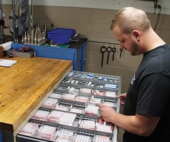
For HMS, the process began with geometrically defining every cutting tool and holder in inventory, starting with those used most often. Today, wider availability of geometric data from suppliers would make this task far easier, Mr. Greenwald says. However, populating the library was only the first step anyway. After ensuring all tool assemblies would be accurately represented in part programs, the shop set about recording feeds, speeds, stepovers and stepdowns for each and every operation on each and every machine.
This might seem tedious, but Mr. Greenwald says it’s likely the only way to determine what works and what doesn’t—that is, to establish a baseline for determining more effective figures for a given cutter/holder/material combination. For HMS, establishing that baseline was often a simple matter of comparing a specific tool assembly’s performance in two different jobs involving the same material, then standardizing on the most effective set of parameters until a better “sweet spot” could be found. “The primary goal is to get everyone cutting the same way, and you have to start somewhere,” Mr. Greenwald says. “Standardizing will expose your weaknesses, and then you can adjust accordingly.”
It’s Not Magic
The shop has a system for finding the best parameters, one rooted in decades of industry-wide, long-accepted machining practices. “We don’t just pull parameters out of a hat and go from there,” he says. “There’s a science to it.”
On the shop floor, machines and people alike tend to convey information in the language of feed rates and spindle speeds. By themselves, however, those figures don’t convey much about what’s actually happening at the cutting edge, he explains. Thus, arriving at a specific number of rotations per minute or inches per minute is never a goal in and of itself. Instead, HMS programmers focus on surface speed and chip load. Typically expressed in surface feet per minute (sfm), surface speed is a measure of how fast an individual cutting edge moves through the material. Too fast, and the edge quickly becomes worn and dull. Chip load is a measure of force on that cutting edge—that is, how much of a “bite” the edge takes on each pass. Too much force, and the edge begins to chip and break.
Industry suppliers have long documented minimum and maximum surface speeds for particular types of cutting tools in particular materials (generally, the harder the material, the lower the recommended surface speed). These widely available figures have historically provided a good starting point for HMS programmers, whether the goal was to revamp existing strategies or to identify parameters for entirely new cutter/material combinations, Mr. Greenwald says. As demonstrated by the formula sfm = effective cutting diameter × [rpm/3.82], surface speed depends on both spindle speed (rpm) and the cutter’s diameter, with a smaller cutter requiring more rotations per minute to achieve the same surface speed as a larger one. Determining the spindle speed required to achieve a specific surface speed is a simple matter of inputting the target number and the cutter’s diameter into the formula.
The shop employs a similar method to determine chip load. That is, programmers use a formula to determine the feed rate (ipm) required to achieve an initial chip load target at the specified surface speed (chip load = ipm/[rpm × number of flutes]). Then, chip load can be adjusted as needed until reaching an acceptable balance between efficiency and reliability. With speeds and feeds locked in, all that remains is to determine the stepovers and stepdowns required to achieve various levels of surface finish.
The Data Reflect the Shop
Mr. Greenwald is understandably reluctant to share parameters that reflect years of experience and painstaking experimentation and data collection. That said, they reflect years of experience in one particular shop, with one particular set of equipment. Thus, even if there is plenty to be gained from examining the shop’s figures, not just anyone could fully carbon copy HMS. Inherent in the shop’s best-practice data is a certain set of assumptions, such as the use of high-speed, internally cooled, direct-drive spindles; constant-chip-load tool paths; certain tool geometries and coatings; and skilled setup personnel. Had HMS been set up differently, its best-practice parameters might be different, too.
The shop’s chosen parameters also reflect its priorities. For instance, heavy focus on unattended machining makes the overall reliability and predictability of the process more important than the raw efficiency of any individual machining routine. As a result, most of the figures trend conservative. “If a machine ends up just sitting there doing nothing at some point during the night because a tool broke, who cares how fast it cuts?” Mr. Greenwald asks. “Our first goal is to keep it going, to ensure it doesn’t stop until the work is done.”
The need for predictability and reliability also explains why the shop has standardized largely on F and V series Makinos despite the fact that some work doesn’t require the full capability of these machines. This mismatch might seem less than optimal, but it makes sense for HMS. In most cases, any job that comes through the door, from a 65-HRC, CPM-M4 mold insert to an aluminum die casting, can be routed to any of these machines with identical, predictable results, Mr. Greenwald explains. If the aluminum die casting doesn’t demand the same rigidity and precision as the mold insert, more aggressive parameters can ensure the part gets finished faster than it could be on a less capable machine.
Improvements Should Stay in the Loop
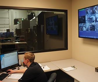
HMS doesn’t have what are usually called machine operators. In fact, the shop floor can be a lonely place even during the single staffed shift, when programmers who aren’t setting up parts rely on video feeds and automatic alerts to stay apprised of what’s happening at their workstations. One lesson of this approach is that an operation truly committed to lights-out—that is, one that can truly eliminate the need for adjustments during the cut—gains not just labor-cost savings, but also an inherent catalyst for continuous improvement. “Real lights-out restores the feedback loop to the programmer,” Mr. Greenwald says, explaining that all critical information from the machine goes directly to the programmer, who can lock any needed change into the process.
The lesson here isn’t just that the database can help take full advantage of this feedback. HMS also makes it a priority to ensure that the loop doesn’t stop after a decision to standardize parameters for a given tool/material combination. The last thing Mr. Greenwald says he wants is a static operation that’s content to lock a set of parameters into the database without ever revisiting, without ever considering how an entirely different cutting tool, or minor tweaks to surface speed and chip load, might affect the machining of a particular material. Indeed, HMS programmers are actively encouraged to make adjustments on their own during their shifts and even to do so aggressively, particularly on low-risk work. “If you’re in an environment where getting too close to the razor’s edge and failing once in a while is unacceptable, you’re never going to improve,” he says. A bonus system based heavily on individual output provides extra incentive to seek new efficiencies, he adds. Any new adjustment is discussed in a group setting to allow everyone to ask questions and provide input before Mr. Greenwald decides whether to standardize on the change.
A Staff with Horsepower
Mr. Greenwald says any shop with suitable CAM software can potentially institute a similar system, and he assumes many have already done so. However, he also believes HMS has an edge that’s difficult to duplicate, particularly when it comes to ensuring parameters continue to improve: an earnest, dedicated staff. “There are mules and then there are stallions, and my people are all stallions,” he says. “They don’t just punch the clock to get by. They’re always pushing, always trying to learn more and make the company better.”
This kind of attitude isn’t Mr. Greenwald’s only priority when it comes to adding new employees. He also values an open mind, preferring neophyte machinists with raw talent to seasoned veterans who might be too set in their ways. Thanks largely to a partnership with the Romeo Engineering Technology Center, a local high school facility dedicated to technical education, he’s found just that on multiple occasions. Indeed, seven of the shop’s nine employees are under the age of 30. Having come to HMS relatively free of preconceived notions, these employees understand the importance of operational consistency, of letting shop-wide practices guide their actions in order to eliminate the variation that naturally results from individuals doing things their own way. Absent this understanding, standardizing on best-practice cutting parameters would be far more difficult, Mr. Greenwald says.
None of this is to suggest that machining experience isn’t valuable. On the contrary, it’s essential, he says. And therein lies another benefit of the parameter system: It helps accelerate learning. “It’s a lot easier to transfer knowledge when a lot of the concepts you’re talking about are embedded in an easily accessible template,” he explains. “And when you’re busy, that template can help anyone be productive, regardless of experience.”
Related Content
Generating a Digital Twin in the CNC
New control technology captures critical data about a machining process and uses it to create a 3D graphical representation of the finished workpiece. This new type of digital twin helps relate machining results to machine performance, leading to better decisions on the shop floor.
Read MoreThe Power of Practical Demonstrations and Projects
Practical work has served Bridgerland Technical College both in preparing its current students for manufacturing jobs and in appealing to new generations of potential machinists.
Read MoreAutomated CAM Programming – Is Your Software Really Delivering?
A look at the latest automation tools in Autodesk Fusion 360 software and how forward-thinking machine shops and manufacturing departments are using them to slash delivery times and win more business.
Read MoreOrthopedic Event Discusses Manufacturing Strategies
At the seminar, representatives from multiple companies discussed strategies for making orthopedic devices accurately and efficiently.
Read MoreRead Next
Building Out a Foundation for Student Machinists
Autodesk and Haas have teamed up to produce an introductory course for students that covers the basics of CAD, CAM and CNC while providing them with a portfolio part.
Read MoreRegistration Now Open for the Precision Machining Technology Show (PMTS) 2025
The precision machining industry’s premier event returns to Cleveland, OH, April 1-3.
Read MoreSetting Up the Building Blocks for a Digital Factory
Woodward Inc. spent over a year developing an API to connect machines to its digital factory. Caron Engineering’s MiConnect has cut most of this process while also granting the shop greater access to machine information.
Read More



.jpg;maxWidth=300;quality=90)
