Should You Balance Your Tools?
Should you balance your tools? The answer varies from process to process. Experience is the best guide.
Ask anyone who has ridden in a centrifuge. As rpm increases, centrifugal force increases even faster. In the same way, any unbalance in a spinning body—say, a milling cutter—generates more force as the body spins faster. In shops making the transition to high speed machining, thoughts quite often turn to tool balance.
Should you balance your tools? A more balanced system of tool, toolholder, and spindle can net several advantages. These range from extended tool life and less downtime for spindle maintenance to tighter machining accuracy and better surface finish (see Figure 1).
But not every shop will realize these benefits, and others will find the cost too high. Tool balancing adds another step in the process—potentially several steps. It typically involves measuring the unbalance of a tool/toolholder assembly (on a tool balance machine), then reducing this unbalance by altering the tool—perhaps by machining it to remove mass, or by moving the counterweights in a balanceable toolholder. The often-iterative procedure can also involve checking the tool again, refining the previous adjustment, and so on until the balance target is achieved.
There is also an inventory cost. Tool and toolholder are balanced as a single unit, so shops performing tool balancing must store and track balanced tool/toolholder assemblies.
In other words, tool balancing—like everything else—merits a cost-benefit analysis. And while new technology may affect the way balancing is performed and justified (see sidebar), the need to perform this analysis is unchanged.
There is no easy answer, says one balance authority. Whether or not to balance, and if so by how much, will vary not just from shop to shop, but from process to process. Take a close look at the application, he advises. Perform test cuts with balanced tools. Only these steps—not any rigid standard—can suggest what level of balancing the process needs.
Unchecked Balance
Mark Stover, manager of business development for Sandvik Coromant, has changed the way a variety of shops engaged in high speed machining think about tool balance. He does so through a presentation based on his company's balancing experience. He recently shared this argument.
A common mistake, he says, is to set a single numerical target for tool unbalance, and apply it broadly across many unrelated processes. Frequently the only result is to penalize these processes with an overly strict—and therefore overly time-consuming—balance requirement.
When is a balance requirement too strict? Mr. Stover gives two answers. One is when the requirement aims to hold the centrifugal force from unbalance to a value significantly lower than the force in the cut. After all, force is force. Why struggle to reduce the unbalance force if the machine will see a much larger repeating force from the cutting edges passing through the workpiece?
The other way the balance requirement can be too strict is when it fails to solve the unbalance problem. "Shops too often assume that balancing the tool will automatically solve any unbalance problem. This isn't necessarily so," Mr. Stover says.
In reality, tool balancing leaves several sources of process instability untouched. One of these is error in the fit between toolholder and spindle taper. "Don't assume you can just pull back, and the taper will line up the same way every time," Mr. Stover explains. There is often a measurable "play" in this clamp, and there also may be a chip or dirt inside the taper. The presence of any such contamination would create unbalance even if the tool, toolholder, and spindle were perfect in every other way.
Math Problems
Mr. Stover cautions against another common mistake, applying a standard to tool balance that isn't right for the job. Tools for milling machines and machining centers, he points out, have little in common with turbine rotors.
Why does this matter? Because the ISO 1940-1 standard often used to set targets for tool and toolholder balance was written not for machine tools, but for rigid rotors—particularly those in power plant turbines.
ISO 1940-1 is the source of the "G class" many engineers will recognize. The lower the G-class number, the better the balance. Many shops, searching for an objective balancing yardstick, establish a G-class target. G2.5 is a commonly used value.
There are two problems with this. Both stem from the two equations at left. Equation 1 defines the maximum unbalance allowed by a given G class. It was derived from the definition of G itself. Equation 2, based on Newton's second law, gives the centrifugal force corresponding to this unbalance. Here is what the equations show:
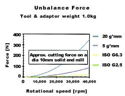
First, G2.5 establishes a balance requirement that will be unduly aggressive for many processes. Take the case of a tool/toolholder assembly weighing 1 kg total, to be used at 12,000 rpm. Equation 1 shows that meeting G2.5 would mean balancing to within 2 g-mm. An aggressive balance? Go to Equation 2. The force corresponding to this maximum allowable unbalance is 3 N.
By comparison, the same tool is likely to see 100 N of cutting force even in a relatively shallow cut. Clearly, the 3 N requirement is therefore rather strict. Figure 2 illustrates the same point.
The second weakness of the ISO 1940-1 standard is that it doesn't behave the way tools behave. Take another look at Equation 1. The equation says that for a given G class, at a constant rpm, increasing the mass of the tool also increases the amount of allowable unbalance. In other words, the balance requirement—as defined by the G-class system—is less critical for a heavier tool.
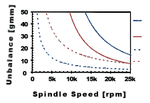
This may give pause to anyone intimate with high speed machining. The balance requirement should be more critical for heavier tools, as Figure 3 suggests. The solid lines in this figure plot data gathered by Sandvik Coromant in an experiment where the unbalance in the tool was gradually increased until it reached the point where process quality suffered. The two curves mark the onset of this degradation. Together they show the effect of switching to a heavier tool, because the two tests they describe were identical except for tool mass.
Compare the trend of the solid lines to the trend of the dashed lines. These plot the unbalance a given G class will allow, as a function of speed, for the same two tool weights.
The trend of the real-life curves runs opposite to what the G-class system assumes. Instead of permitting more unbalance, heavier tools actually demand less. This disagreement suggests that tool balance targets won't be realistic if G classes are used to define them.
So what is a better measure of acceptable unbalance?
Experience
No single standard applied throughout the shop will do, Mr. Stover says. Experience, gained through experimentation, is the best guide. Balancing requirements are better evaluated one process at a time—so long as the process will be repeated enough to make some experimentation a worthwhile investment.
Step one is to evaluate whether balancing is warranted. Can the cutting force be determined? If so, compare that force to the one likely to result from an unbalanced tool. To estimate this, measure several tool/toolholder assemblies in search of a maximum realistic unbalance, then calculate the force corresponding to this using Equation 2 (above).
Mr. Stover offers this rule of thumb: So long as the total unbalance force is less than the cutting force, further balancing is unlikely to improve the process.
This rule can't decisively answer the question of whether to balance for at least two reasons. First, many processes will be exceptions. Those with very smooth surface finish requirements, as well as airframe production processes in the neighborhood of 50,000 rpm, will both require lower unbalance. Second, the amount of unbalance over and above tool unbalance can be difficult to pin down.
However, the rule does suggest that tool balancing probably is not justified when the tool unbalance force is far less than the force in the cut.
Instead, for many high speed machining processes, just aiming for good balance through proper tool selection is sufficient. This is largely a matter of attention to detail, Mr. Stover says. He gives these three tips:
- Buy quality tools and toolholders. Look for toolholders that have been premachined to remove unbalance.
- Favor tools that are as short and as lightweight as possible.
- Regularly inspect tools and toolholders for fatigue cracks and signs of distortion.
Following these steps can go a long way toward improving tool balance, whether or not a separate balancing step is part of the process.
The Right Balance
But where tool balancing is warranted, the next step is to determine how much unbalance is acceptable. There is no substitute for trial-and-error within the actual process, says Mr. Stover. The tool unbalance that the process can accept is determined by other aspects of the process itself. These include the forces in the cut, the balance condition of the machine, and the extent to which these two affect one another.
To find the right unbalance target, run the intended operation several times, using tools balanced to a variety of different values—say, from 20 g-mm on down. After each run, upgrade to a more balanced tool and repeat. The optimal balance is the point beyond which further improvements in tool balance fail to improve the accuracy or surface finish of the workpiece, or the point at which the process can easily hold the specified workpiece tolerances.
The key is to stay focused on the process. Don't aim for a G value or any other arbitrary balance target, he says. Instead, aim to achieve the most effective process possible. This involves weighing the costs of tool balancing against the benefits it can deliver, and striking the right balance between them.
Related Content
Toolpath Improves Chip Management for Swiss-Type Lathes
This simple change to a Swiss-type turning machine’s toolpath can dramatically improve its ability to manage chips.
Read More10 Ways Additive Manufacturing and Machining Go Together and Affect One Another
Forget “additive versus subtractive.” Machining and metal additive manufacturing are interconnected, and enhance the possibilities for one another. Here is a look at just some of the ways additive and machining interrelate right now.
Read MoreOrthopedic Event Discusses Manufacturing Strategies
At the seminar, representatives from multiple companies discussed strategies for making orthopedic devices accurately and efficiently.
Read MoreHigh-Feed Machining Dominates Cutting Tool Event
At its New Product Rollout, Ingersoll showcased a number of options for high-feed machining, demonstrating the strategy’s growing footprint in the industry.
Read MoreRead Next
The Future of High Feed Milling in Modern Manufacturing
Achieve higher metal removal rates and enhanced predictability with ISCAR’s advanced high-feed milling tools — optimized for today’s competitive global market.
Read More5 Rules of Thumb for Buying CNC Machine Tools
Use these tips to carefully plan your machine tool purchases and to avoid regretting your decision later.
Read MoreRego-Fix’s Center for Machining Excellence Promotes Collaboration
The new space includes a showroom, office spaces and an auditorium that will enhance its work with its technical partners.
Read More








.jpg;maxWidth=300;quality=90)


.jpg;maxWidth=300;quality=90)


