Setting the Stage for Sizeable Composites Work
By adding a five-axis waterjet/milling machine, its biggest autoclave and a more expansive lay-up room, Royal Engineered Composites is positioning itself to win larger-scale aerospace work it sees on the horizon.
Share


Some might say that Royal Engineered Composites sits in the middle of nowhere, but don’t let its location fool you. The Minden, Neb., manufacturer has impressive composite production capabilities and has recently made significant strides to process larger-scale parts in the future.
Tim O’Dey, engineering manager, says Royal was spurred to expand its capacity to take on this type of work a few years ago, sensing an upcoming need for suppliers of big composite aerospace components such as engine cowling sections and thrust-reverser systems. But while the company had a wealth of experience manufacturing similar, smaller-sized composite components, its existing production capabilities simply couldn’t accommodate work of that magnitude. Given its vertically integrated approach, scaling up its process would require a considerable investment in a number of areas so as to keep complete composite manufacturing capabilities in-house.
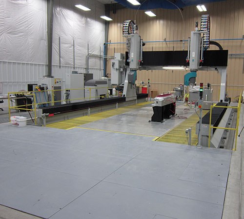
In a bold move to position itself to win this type of work, Royal recently completed the first of three planned facility expansions. This first expansion increased its total floor space to 82,000 square feet with a high-bay building addition that includes a larger composite lay-up clean room, its sixth and biggest autoclave, and a combined five-axis waterjet/milling machine for final trimming and drilling operations. What’s particularly impressive is that the company made these investments without having POs in hand for the type of large-sized production work it believes will come.
LARGE ADDITIONS
Royal Engineered Composites began as Royal Plastic in 1949, specializing in plastics thermoforming. It changed its name in 2010 because its focus has shifted to structural composite components, primarily for aerospace parts such as thrust-reverser doors, sandwich panel components, fairings and radomes.
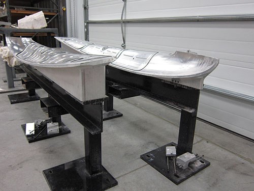
Typically, the manufacturing process for a composite component starts by CNC-cutting individual composite plies that are kitted and delivered to a clean room for hand lay-up in molds. Some of Royal’s clean rooms have laser projectors installed in their ceilings that precisely project a laser outline onto lay-up molds to show workers where individual plies are to be positioned. Once lay-up is complete, the component is placedin a Mylar bag and delivered to an autoclave, which applies heat and pressure in a nitrogen-filled environment to cure the component. Once curing is complete, the component is removed from the bag, its periphery is trimmed, and holes might be drilled, depending on the application. Some customers ask Royal to perform component assembly while others prefer to assemble components themselves.
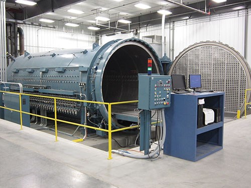
Every element of this manufacturing process needed to be supersized in order for the company to accommodate the larger work it envisions. For instance, its new autoclave from ASC Process Systems is significantly bigger than the shop’s five other autoclaves. Installed in the fall of 2013, the unit is 12 feet in diameter and 30 feet long. Mr. O’Dey says it is the largest ASC autoclave that can be installed in a facility without needing to be built on site. Royal’s formerly largest autoclave measured 8 feet in diameter and 16-feet long.
Not only will the new autoclave be used to cure larger parts, but it will also be able to handle a greater number of smaller parts per curing cycle than the shop’s other units. It has many more vacuum and thermocouple ports to enable that as well as a safety system that completely purges the nitrogen out of the unit before the door can be opened. Otherwise, the significant volume of nitrogen that would escape could cause someone standing nearby to pass out.
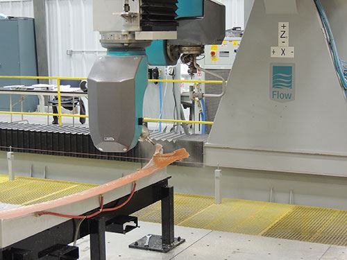
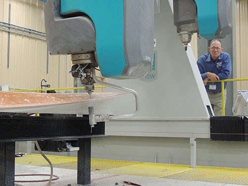
In the past, Royal performed trimming, drilling and countersinking work on CNC routers or conventional machine tools. To accommodate larger parts, the company added a Composites Machining Center (CMC) from Flow Aerospace Systems that performs both five-axis waterjet cutting and conventional milling, and offers XYZ travels measuring 21.3 by 8.2 by 3.3 feet.
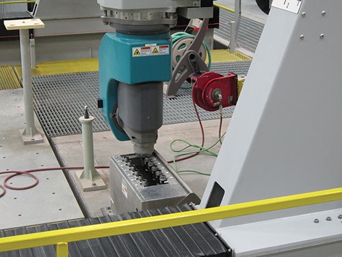
Based on a design that originated in 1991, this CMC is a gantry-style machine with dual five-axis waterjet and milling spindle heads. Mark Saberton, chief engineer for Flow, says this unit is the first of the OEM’s Size B models to be installed in the United States, and reflects a number of design improvements compared to past models. For instance, Flow used today’s more advanced finite element analysis capabilities to remove weight from the machine structure while maintaining rigidity and increasing speed. Digital servos on machine axes have also helped increase speed as well as positioning accuracy, while the refined, Catia-based FlowTrim programming software enables offline simulation to detect possible collisions prior to performing actual cutting operations.
The Size B version also features a modular design that enables additional X-axis rails to be added to extend the machine’s longitudinal travel. In fact, the foundation Royal created for the CMC allows for those additions to be made without additional excavation if the company chooses to do so in the future. The CMC is also set up to easily add Flow’s Flexible Header System. This reconfigurable fixturing system has multiple actuators that can be raised to different Z-axis heights to accommodate contoured components, each using vacuum cups to secure components during machining. This system could replace or minimize the need for traditional vacuum fixtures.
WATERJETTING OR CONVENTIONAL CUTTING?
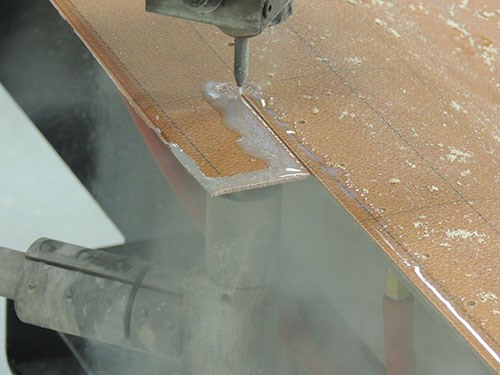
Mr. O’Dey says Royal was drawn to high-pressure abrasive waterjet cutting because it offers specific advantages for machining composite materials such as carbon fiber reinforced plastic (CFRP), Kevlar and quartz-epoxy composite. Garnet abrasive media serve as a waterjet stream’s “cutting edges.” Because fresh media is continually introduced into the stream, the stream’s cutting edges are always sharp, whereas conventional routing and drill bits can wear, possibly resulting in delamination or burred edge finishes. Worn tools can also introduce heat into the part, which is problematic because composite materials have a particularly hard time dissipating heat. No sizeable chip is generated to carry the heat away from the low-thermal-conductive material, so heat buildup poses the danger of burning the resin.
The cutting forces for waterjet machining are one-tenth or less than conventional machining, too. This means fixtures for components machined via waterjet need not be as bulky as those required for conventional milling. Managing dust isn’t an issue with waterjet as it can be with conventional milling operations for composites, either (although later in the article we’ll touch on a dust control system Flow has developed for the CMC’s milling head that is particularly effective in that regard).
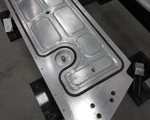
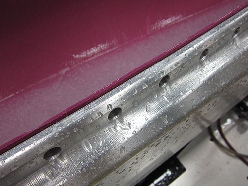
The CMC’s waterjet head differs from those used on typical waterjet equipment. Conventional machines have a tank of water under their cutting bed grates to absorb the waterjet stream after it pierces through a workpiece. Conversely, the CMC has no water tank, but a solid steel bed that’s flush with the shop floor. Its waterjet head includes a “catcher cup” to receive the jet after it shoots through a workpiece. The catcher cup collects machining waste and vacuums it into a separating filter. It also prevents the jet from unintentionally cutting through some other area of the workpiece or injuring shopfloor personnel.
This C-shaped catcher cup must be taken into consideration when designing waterjet fixturing, however. Fixtures must provide access on the back side of the workpiece to leave room for the cup. That said, there are some applications in which only a portion of the workpiece can be machined via waterjet due to interference with the cup. In those cases, work must be completed using the CMC’s milling head.
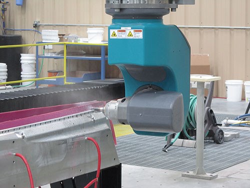
High power and torque is generally not needed for machining composite materials, so Royal’s CMC milling head features an 8-hp, 25,000-rpm spindle. The company has found running between 7,500 and 8,000 rpm to be particularly effective for routing/trimming operations on most composite materials. Balanced, HSK 40A shrink-fit toolholders are used to minimize tool runout. Royal initially used balanced, collet-style toolholders, however the cutters would wear non-uniformly. The company has eliminated that problem by switching to shrink-fit toolholders.
Royal has had success using tools such as 10-flute CVD-diamond-coated routing bits from Crystallume for trimming operations. Sharp cutting edges combined with an abrasion-resistant diamond coating enable these tools to effectively shear through composite fibers to leave behind a quality edge finish while achieving long life. Because most of the composite workpieces are relatively thin, the company will routinely alter the depth that a tool reaches through a workpiece to get the most out of the tool’s total available flute length.
The CMC also includes a 12-station toolchanger. During tool changes, filtered air blasts delivered through the spindle and out of the toolchanger keep contaminants out of the spindle. A new system Flow developed helps manage the dust that is created during milling operations, too. Rather than using a vacuum-based dust evacuation system, the new design combines cool air and mist delivery to contain the dust. The proprietary system generates a collimated stream of cold air that is delivered to the tool (not through it). Unlike coolant alone, the cold-air stream is able to penetrate what is effectively an air barrier that surrounds tools running at high rpms. This enables the plume of mist that is delivered to knock down the dust and subsequently be hosed off the machine bed. The system cools the tool and the composite workpiece, too.
FUTURE PLANS
Royal still faces a bit of a learning curve with the CMC in terms of optimizing fixture design. The company might also upgrade the machine’s probing capability. The current probing package is used to accurately locate fixtures on the machine’s bed during setups. This is done by probing various locating balls that are machined into fixtures. However, it might upgrade the package to enable in-process measurement. This would be particularly helpful to verify that countersinking operations for rivet-assembly holes reach their specified depth and don’t protrude above a component’s surface, which would cause drag during flight.
Mr. O’Dey says he envisions adding a crane in the new building addition to more easily transport and install large fixtures onto the CMC, too. But he also hinted that a return trip on my part might be warranted down the line to see the results of another process improvement. The company may soon begin using iPads or other tablets on the shop floor in an effort to go paperless and ensure that all necessary job information is readily available to shopfloor personnel. So I may very well end up returning to the middle of nowhere again.
Related Content
The Role of Surface Finishing in Modern Manufacturing: Trends and Best Practices
You’re attending IMTS to advance your business. Regardless of your role in the manufacturing process, considering how your parts will be finished is crucial. This article can help you understand trends in surface finishing and better communicate with your finishing partners.
Read MoreHow to Meet Aerospace’s Material Challenges and More at IMTS
Succeeding in aerospace manufacturing requires high-performing processes paired with high-performance machine tools. IMTS can help you find both.
Read MoreForkardt Hardinge Swiss Workholding Provides Reliable, Consistent Performance
The company’s Swiss collets are designed to securely hold parts without marring surfaces, minimizing vibration to ensure smoother machining, enhanced accuracy and extended tool life.
Read MoreSandvik Coromant Inserts Provide Stable Turning of Aerospace Components
The new insert grades GC1205 and GC1210 cover a large application area within last-stage machining and intermediate-stage machining when turning aerospace engine components.
Read MoreRead Next
Setting Up the Building Blocks for a Digital Factory
Woodward Inc. spent over a year developing an API to connect machines to its digital factory. Caron Engineering’s MiConnect has cut most of this process while also granting the shop greater access to machine information.
Read MoreBuilding Out a Foundation for Student Machinists
Autodesk and Haas have teamed up to produce an introductory course for students that covers the basics of CAD, CAM and CNC while providing them with a portfolio part.
Read MoreRegistration Now Open for the Precision Machining Technology Show (PMTS) 2025
The precision machining industry’s premier event returns to Cleveland, OH, April 1-3.
Read More



.png;maxWidth=300;quality=90)


