Raising the Bar with Ballbar Testing
Few manufacturing companies rely on ballbar testing to maintain machine tool accuracy as thoroughly as Silfex. Now, advanced training and a move to a Renishaw QC20-W wireless system have enabled the company to take the benefits of ballbar testing to a higher level.
Share


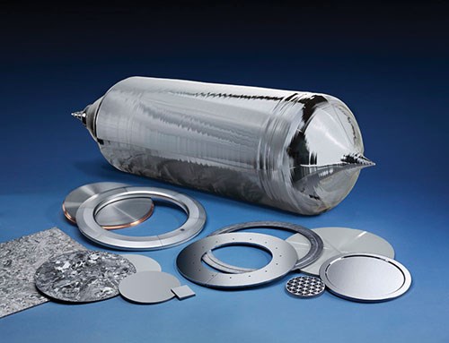
Several vital characteristics make Silfex stand out as a manufacturing company. It is one of the few firms in the world capable of producing high-quality silicon components for the semiconductor industry. It utilizes a unique variety of manufacturing processes, including wire sawing, waterjet cutting, milling, drilling, grinding and lap polishing, to produce these parts start-to-finish under one roof at its Eaton, Ohio, facility. One of these processes uses conventional VMCs to grind disks of pure silicon. The harsh machining environment created by this operation has compelled the company to be exceptionally vigilant at monitoring the capability of these machines because ballscrews and other machine components are subject to rapid wear from the abrasive particles of silicon. Frequent and regular use of a ballbar testing device has helped shop personnel ensure the capability of these machines, which often involve maintaining tolerances of ±0.0010 inch, and some as tight as ±0.0005 inch.
Silfex’s disciplined program of regular ballbar testing makes it a model for other machining companies, few of which take such thorough advantage of this simple, but effective way to diagnose the “health” of CNC machine tools. Other shops have even more to learn from Silfex now that it has benefited from advanced ballbar training with Renishaw (Hoffman Estates, Ill.), the supplier of the system used so well in the Eaton facility. And, by upgrading to a wireless ballbar system, Silfex has become a showcase for the latest advances in ballbar technology.
“Although we’ve done ballbar testing for years and have enjoyed great success in maintaining the capability of our machining centers as a result, we weren’t making full use of the test results,” says Wayne Ross, head of Silfex’s total predictive maintenance (TPM) program. The additional skills and insights developed at the advanced training class have changed that. He and Jacob Hebbeler, production machinist and lead ballbar specialist, agree that regular use of the testing device has become more valuable than ever.
“We can interpret the ballbar data more deeply and apply the results more effectively to keep up with changing demands in our plant,” Mr. Hebbeler says. In addition to coping with the effects of exceptionally harsh machining conditions, ballbar testing helps Silfex extend the life of its machines, avoid premature replacement of worn components, assign machines to operations that match their capability, and get machines back in production quickly when business growth requires expansion and rearrangement of machines on the production floor.
As a leading producer of components used in the manufacture of semiconductors, Silfex has a design and engineering staff that continually pushes the envelope in product complexity and quality. “We can keep up with growing requirements for greater accuracy, more product diversity, shorter runs and faster change-over in our manufacturing operations because we have implemented lean manufacturing techniques, statistical process control and TPM,” says Mr. Ross. “Ballbar testing is an essential and integral part of the ongoing development of these programs. Our experience shows why machine shops of all kinds should consider making ballbar testing part of their routine,” he says.
No Defects at Silfex
Silfex is a rapidly growing division of Lam Research Corp., a supplier of highly sophisticated wafer fabrication systems that electronic chipmakers use to produce increasingly complex devices on an increasingly miniature scale. With headquarters in Fremont, Calif., Lam Research is strategically located near the fabled Silicon Valley, the
country’s epicenter of semiconductor research and production.
Silfex got its start more than 30 years ago as Bullen Ultrasonics, a small, family-run business that specialized in ultrasonic machine technology. Over the years, the company developed proprietary machining methods to match the demands of applications that required high precision processing. Its process of ultrasonic impact grinding proved especially successful, leading to significant growth. To support increasing requirements for a high mix of custom materials in small batches, the company introduced silicon crystal manufacturing and soon became a major producer of large billets of single-crystal silicon. Silfex says it is one of the few companies in the world that can produce defect-free silicon as a single crystal as large as 460 mm in diameter.
In 2006, Lam Research, one of Bullen Ultrasonics’ major customers, purchased the company’s silicon growing and fabrication capabilities to help ensure availability of proprietary components essential to the performance of Lam’s semiconductor etch chambers. In 2012, Silfex completed a large-scale expansion of the silicon growing capacity and greatly enlarged its capability in bonding, cleaning and packaging finished products. In addition to serving the semiconductor market, the company now supplies high-purity, custom silicon components and assemblies to other high-technology customers for electronics testing, solar energy and optical applications.
Most of the CNC machine tools at Silfex are dedicated to the production of silicon and quartz components, mainly consumable parts that support the etching process in that manufacturer of computer chips. More than 50 VMCs are now in place, arranged in several cells to support roughing and finishing operations. Although these VMCs—primarily Haas and Mazak models—are standard conventional machines, they use specialized tooling to grind and polish silicon and quartz. As a result, they are subject to the effects of having the abrasive grinding swarf and coolant infiltrate the mechanical systems inside the machine structure. Mr. Ross likens the mix of silicon or quartz particles and coolant to a lapping compound or polishing slurry. “This naturally creates a high-wear environment for ballscrews, linear guide rails and thrust bearings,” he says, noting that these effects are compounded by the productivity expected of these machines. “We run these machines hard, three shifts a day and five days a week.”
Not surprisingly, as the company developed these unconventional processes, monitoring the capabilities of these machines closely to maintain workpiece accuracy became urgent. According to Mr. Ross, ballbar testing was originally introduced about 14 years ago. Mr. Hebbeler, then one of the younger machinists on the line, was trained to use this device. He soon became the shop’s main ballbar specialist,and was frequently called upon to conduct the ballbar test.
“The ballbar gave us a reliable picture of what was happening if and when we detected wear of ballscrews or other components. We wanted to track changes in the machine’s capability well in advance of signs that might appear in workpiece inspection data,” Mr. Hebbeler explains.
Historically, ballbar testing gave Silfex options that it might not have without this technology as part of its monitoring routines. For example, the shop could track signs of ballscrew wear and move the rough grinding operations, which generally required a lesser degree of accuracy, to “looser” machines, while retaining the tightly toleranced finishing operations on machines with the appropriate capability. Likewise, ballbar testing provided certainty in decisions to replace worn components. “We didn’t have to guess or jump the gun in the interest of an overly wide safety margin,” Mr. Ross says.
At the time, Mr. Ross recalls wondering how any shop could manage without the availability of a ballbar testing system as an in-house check on machine performance. “In line with our program of continuous improvement, Jacob and I elected to attend the advanced ballbar class,” he says. Offered at at Renishaw’s U.S. headquarters in Hoffman Estates, about 20 minutes northwest of Chicago’s O’Hare airport. The course involved 3 1/2 days of classroom instruction, hands-on training and product demonstrations. They completed the course in November 2012. The pair quickly realized the experience would enhance the benefits of ballbar testing at the shop in Eaton.
“Among other things, we learned how to troubleshoot scale mismatch, which has helped us super tune our circular interpretation and extend the useful life of the mechanical parts of our machines. We also look at lateral play to gage the condition of our linear guides.”
“After the advanced class we concentrated on interpreting our numbers to see if there were more details we could control,” Mr. Ross explains. “Jacob has gotten really good at adjusting the backlash and reversal spikes, so we can get more life out of the ballscrews, which is our hedge until we can get a service technician to come. Sometimes we can do two or three adjustments, and that buys us a lot of productive time to schedule when to take the machine offline for repair.”
Same Operation, Better Interpretation
Clearly, the payoff of the advanced training was in the interpretation of ballbar data and applying these insights more effectively. “We use the ballbar on a more regular basis, that’s for sure,” Mr. Hebbeler says. “But basically, the testing procedure is the same, although the more frequent practice has made us more efficient.” The new wireless system further streamlines the operation. Ballbar testing at the machine takes about half an hour, he reports. Depending on the results and their immediate analysis, adjustments to the machine may entail 30 more minutes, or occasionally another hour or two.
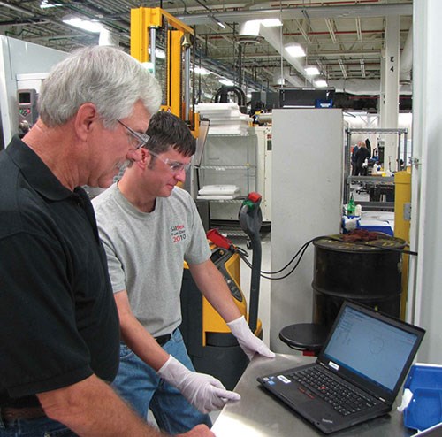
Mr. Hebbeler has the ballbar kit stored on a wheeled cart that can be easily rolled to any machine for testing. A laptop computer for recording, analyzing and displaying test results sits on the top tray of the cart alongside the padded case for the ballbar apparatus. A digital level and some tools most frequently used to adjust the machine-tool level are stored in the lower tray of the cart.
Ballbar Basics—Running around in Circles
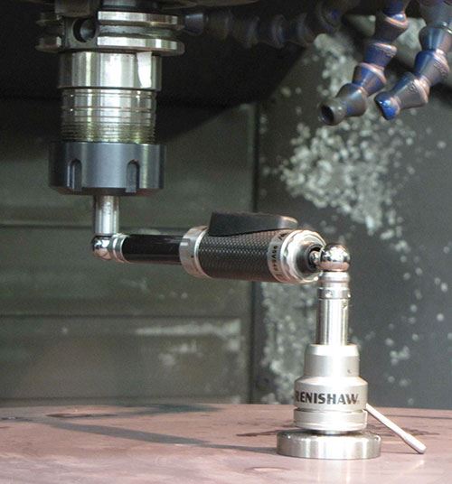
A ballbar testing system has three main components: the ballbar, a precision magnetic mount that attaches to the machine table, and a second precision magnetic mount that attaches to the machine spindle or spindle housing. The ballbar is, as its name implies, a telescoping bar with precision balls at each end. Transducers within the bar detect the in and out movement of the telescoping components. After attaching the mounts to the table and spindle, the balls of the sensor bar are kinematically located in the magnetic cups on the face of each mount. This arrangement enables the ballbar to measure minute variations in radius as the machine follows a programmed circular path around the mount on the machine table.
The basic ballbar test calls for the machine to perform two consecutive circles—one in a clockwise direction, the other in a counterclockwise direction. In theory, a machine with perfect positioning performance would move in a circular path that exactly matched the program circle. In reality, many factors in the geometry of the machine structure, the capability of the control system, wear in the moving components of machine axes and so on, cause variations in the radius of the test circle. These variations result in a path that deviates from the perfect, programmed circle.
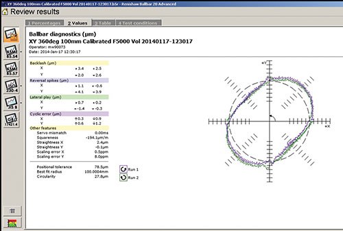
As the sensors in the ballbar capture the variations in the radius and transmits them wirelessly to the laptop, the ballbar software records these deviations, displays them in comparison to a perfect circle and analyzes the results as a report that can be viewed at the machine immediately after completing the test procedure.
Being Right About What’s Wrong
The almost instantaneous report generated by a ballbar test provides a diagnostic review of the machine’s capability in critical areas. One of the indicators that now gets more attention is scaling mismatch, an error resulting from the difference in the measured travels of the X and Y axes during the ballbar test. It is a sign that one of the machine axes is either over-traveling or under-traveling relative to the other. “In our experience, scaling mismatch generally means that the ballscrews are making the correct number of rotations, but wear in the threads and ballnut is not enabling the ballnut to reach the distance intended,” Mr. Ross explains.
Fortunately, scaling mismatch is fairly easy to correct, especially on the Haas VMCs, he reports. “We simply go into the table of machine settings at the CNC and enter a new value for the linear error compensation parameter. This enables the control to treat the feedback from the ballscrew’s rotary encoder as if the ballscrew had a slightly smaller or larger pitch.” Making this adjustment to compensation tables on machines with other types of CNCs is more complicated, but yields the same correction. Troubleshooting scaling mismatch improves circular interpolation by the CNC, resulting in more accurate machining of curves and arcs.
Lateral play is another diagnostic reading that Mr. Ross and Mr. Hebbeler check more closely now. “We look at lateral play to gage the condition of our linear guides,” Mr. Hebbeler says. This indicates that possible wear to the rails of the guideways is allowing the axis to move at a slight angle away from perpendicular on one or both sides. “A simple way to say it is that the machine table is crooked even though the axis drive may be moving it in the correct path, because travel is dragging on one side or leading on the other,” Mr. Hebbeler says.
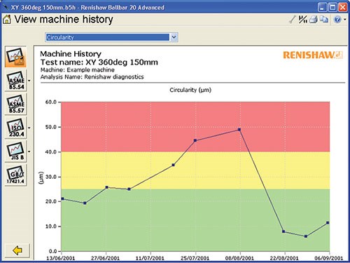
A history of these readings tells the shop when major repairs or replacement of linear guides is necessary. Improving the way covers is another point of focus for prolonging the life of ballscrews and linear guides, Mr. Ross adds.
Getting Squareness Squared Away
Gaining a deeper understanding of certain ballbar test readings is one more outcome of the advanced training. Chiefly, this pertains to squareness as an indicator of conditions in the machine’s lower structure. “We’ve learned that squareness issues are most commonly caused by inadequate leveling of the machine. What we appreciate now is how important it is to level a machine thoroughly when it is installed or moved and to check machine level consistently,” Mr. Ross says.
Squareness error indicates that the angle between the two axes in the test plane is not perfectly at 90 degrees. The values from this error indicate the direction and severity of out-of-squareness. “This gives us a starting point for checking the machine with digital levels. We now use levels accurate to within ±0.001 degree. What we usually find is that there is a dip in one corner of the machine base. Often, an eighth of a turn to one or two leveling screws is all it takes to correct squareness, which we verify with another ballbar test,” says Mr. Hebbeler.
Determining machine squareness is a prerequisite for analyzing backlash, reversal errors and scaling mismatch, so it is usually the first diagnostic that gets scrutiny. When a new machine is placed on the floor or when an existing machine is relocated, Mr. Ross and Mr. Hebbeler have its leveling checked and adjusted thoroughly. They level a new machine before the factory installers do their final check, and they recheck it again after the machine “relaxes” and settles in place.
“We can routinely hit squareness figures that are finer than factory specs or what the installers can achieve,” Mr. Hebbeler says. In fact, he and Mr. Ross strive for a squareness accuracy of 0.000025 inch per inch, a goal that virtually guarantees they will exceed their prior target of 0.000050 inch per inch. This constant emphasis on squareness provides a head start on checking and maintaining other aspects of a machine’s accuracy.
For example, this approach adds greater confidence to the values entered to adjust for backlash and reversal spikes. Tracking these adjustments tells the shop when room to compensate for backlash in the ballscrew is running out. Likewise, when approaching a similar limit to correcting for reversal spikes, the shop knows that thrust bearings in ballscrew mounts need replacement. These events can be scheduled to minimize the impact of the machine downtime.
More To Explore
These enhanced benefits from ballbar testing have inspired the company to explore other possibilities. “The ballbar tells us about the machine’s foundation: the linear guides, the ballscrews and the thrust bearings—the bottom end of the machine—that’s where mechanical tolerances are established and it also confirms our metrology,” Mr. Ross says. “We’ve also started using some vibration analysis, and that tells us about the upper portion of the machine, which dictates finish. So, between the two, we are analyzing all the factors that affect our size and finish.” Measuring volumetric accuracy with the ballbar is the next priority. “We currently test X and Y on VMCs, and X and Z on the lathes, and have done full Y-Z and X-Z testing in the past on a few machining centers. With volumetric testing, we’ll also hit X-Z and I think we’ll be able to get what we need in the 220-degree X-Z sweep the ballbar is capable of.”
Silfex is also using ballbar data to establish thresholds in relation to its various processes and determine process capability. “We now have diagnostics to back up what we think is happening with our machines,” says Mr. Ross. “This data is being used for our TPM program, implementation of SPC and our future OEE monitoring. Full SPC will allow us to move away from 100-percent inspection. We are also working to determine what will be the useful life of a machine based on capability, maintenance costs and consistent quality.”
Finally, Mr. Ross explains that components leaving the machining area often proceed to manufacturing processes that, by their nature, are difficult to control simply because of the laws of chemistry and physics. For example, an acid etching step that follows machining is extremely sensitive and subject to many environmental variables for which the science is still evolving.
“The accuracy we achieve in machining gives engineers a cushion that protects the tolerances on these components under the very demanding conditions encountered in downstream processing. And that protects our customers who are end users of our wafer fabrication systems. This is the ultimate value for leveraging every machining technology at our disposal. The world revolves around numbers, and ballbar analysis is our magnifying glass to help make good business decisions,” Mr. Ross concludes.
Related Content
How to Evaluate Measurement Uncertainty
Manufacturing and measurement are closely coupled. An important consideration for the use of measurement results is the associated measurement uncertainty. This article describes common metrology terms and provides an example uncertainty analysis.
Read MoreParts and Programs: Setup for Success
Tips for program and work setups that can simplify adjustments and troubleshooting.
Read MoreChoosing the Correct Gage Type for Groove Inspection
Grooves play a critical functional role for seal rings and retainer rings, so good gaging practices are a must.
Read MoreHelp Operators Understand Sizing Adjustments
Even when CNCs are equipped with automatic post-process gaging systems, there are always a few important adjustments that must be done manually. Don’t take operators understanding these adjustments for granted.
Read MoreRead Next
Building Out a Foundation for Student Machinists
Autodesk and Haas have teamed up to produce an introductory course for students that covers the basics of CAD, CAM and CNC while providing them with a portfolio part.
Read More5 Rules of Thumb for Buying CNC Machine Tools
Use these tips to carefully plan your machine tool purchases and to avoid regretting your decision later.
Read MoreSetting Up the Building Blocks for a Digital Factory
Woodward Inc. spent over a year developing an API to connect machines to its digital factory. Caron Engineering’s MiConnect has cut most of this process while also granting the shop greater access to machine information.
Read More



.jpg;maxWidth=300;quality=90)


