
Balancing MfAM and DfAM for Metal Additive Manufacturing
For viable metal AM, users must balance design for additive manufacturing (DfAM), modifying for additive manufacturing (MfAM) and cost per kilogram.

Share


Takumi USA
Featured Content
View More.png;maxWidth=45;format=webp)
DMG MORI - Cincinnati
Featured Content
View More


Hwacheon Machinery America, Inc.
Featured Content
View More


This past month, I was fortunate to work with a company on a “culminating” experience as part of their internal training for additive manufacturing (AM). Like many companies I work with, they had identified a part through a screening process, using filtering criteria akin to what I wrote about a few months ago. As you might guess, the result was a set of parts that could be made with AM, but the economics were not compelling to replicate the part with AM — a good reminder that “can” and “should” are two very different questions when it comes to AM.
After several discussions, we decided to use one of the parts as the candidate for the course and challenge participants to apply the learnings and tools from their introductory and intermediate AM training courses to this part. In this way, it became a win-win for the participants and the company. The participants got to work on a real part in the course while the company leveraged some of its training budget to start to redesign a part for AM.


While I am not allowed to share any details about the company, the part, or its cost, I can share some details on the pathways that participants took to try to realize a viable AM part. As shown below, it began by establishing an estimate of what it would cost to replicate the part “as is” with AM. As we have talked about many times before, this “like for like” substitution that companies attempt at the start of their AM journey is the hardest to justify, and we can see why in the figure.
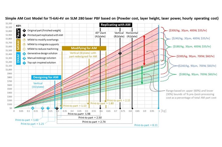
Simple AM cost model. Image credit: Timothy W. Simpson.
Using my simple AM cost model, participants plotted $/kg as I outlined in last month’s column for laser powder bed fusion. In this case, process parameter data were obtained for Ti-6Al-4V ELI (Grade 23) from SLM Solutions’ website. There are four processing conditions for this material on the SLM®280 2.0 system, and the figure plots the slowest and cheapest settings (30-mm layers, 400 W laser power, $35/hr to operate the machine) as well as the fastest and most expensive settings (90-mm, 700 W, $60/hr) to bound our cost estimates. Pre-/post-processing costs were varied from 60 percent to 30 percent as indicated in the figure, and powder costs and hourly machine operating costs are based on ballparks from my experiences the past five years in CIMP-3D. The resulting $/kg plot gave participants immediate insight into the tradeoffs that they would have to navigate as they redesign the part — some of which are in their control (such as part weight and extent of pre-/post-processing), some are not (such as powder cost, processing parameters, hourly operating cost) — for AM.
Armed with this plot, the challenge of replicating the part with AM become evident quickly. While the original part (indicated by “0”) weighs less than 0.3 kg, support structures, machining allowances and other stock additions for different build orientations more than double the amount of material that is printed, driving costs up substantially. Three build orientations are plotted in the chart for illustration: (1) horizontal minimizes build height but only allows four parts per build plate, (2) vertical minimizes the footprint on the build plate, allowing eight parts to be printed at once and (3) slanted 45o minimizes supports but only allows four parts per plate.
At this point, the vertical orientation was selected to maximize production quantity per build, and the estimated cost to replicate the part “as is” is indicated by the “1” in the figure. This point became the baseline cost for comparison (not “0”) as the part was redesigned. In this case, the “print-to-part” ratio became a key metric since it was difficult to justify printing 2.5 times the material and then machining away the excess to replicate the part weight. Granted, the original part had a buy-to-fly ratio of about 9:1, but the high print-to-part ratio for this orientation meant it was time to shift to modifying for AM (MfAM) to drive costs out.
There are many creative ways to reduce costs and modify a part for AM, and three solutions are plotted in the figure, labeled “A”, “B” and “C”. All three are in the vertical build orientation, but participants leveraged the design freedom we gave them to modify overhangs, minimize and even integrate support structures into the part, and refine stock additions/machining allowances to reduce post-processing costs. These modifications reduced the print-to-part ratio from 2.50 down to 2.15, 1.80 and 1.13, respectively; however, participants also identified opportunities to reduce the weight of the part as well by reviewing the structural analysis results.
This realization led to the final phase of the “capstone” experience, wherein participants sought to add value by applying design for AM (DfAM) methods, such as topology optimization and generative design. Participants applied different techniques based on their level of proficiency with CAD and different DfAM software tools. Three solutions are shown in the figure to illustrate some of the results. The lightest-weight solution, “a”, was obtained using a generative design tool, but the organic shape required excessive support structures. So, while this solution reduces weight by nearly 60 percent, the corresponding print-to-part ratio is 8.11, which was unacceptable. Solution “b” was obtained by manually modifying the CAD model based on the structural analysis results — removing material in low-stress regions of the part. This reduced the weight of the part by about 30 percent, but the corresponding print-to-part ratio was 1.60, which was still quite high.
The best solution of the three shown reduced the weight by 20 percent while achieving a print-to-part ratio of 1.21, indicated by “g” in the figure. This solution was obtained by balancing DfAM and MfAM, specifically, using topology optimization to inspire modifications to the original part while also considering relevant design guidelines, reducing support structures, and minimizing post-processing. The reduced weight of the part offsets the additional material that is printed for supports and such, yielding a solution that achieves cost parity based on the original part weight (“0” in the figure) and opening a pathway to a viable AM part. Now the real work begins!


Related Content

The Benefits of Vertically Integrating Metal 3D Printing and Machining
Having 3D printing and machining within one organization enables Addman’s engineers to collaborate and consolidate so it can quickly make successful metal 3D printed parts.
Read More
Chuck Jaws Achieve 77% Weight Reduction Through 3D Printing
Alpha Precision Group (APG) has developed an innovative workholding design for faster spindle speeds through sinter-based additive manufacturing.
Read More
Additive/Subtractive Hybrid CNC Machine Tools Continue to Make Gains (Includes Video)
The hybrid machine tool is an idea that continues to advance. Two important developments of recent years expand the possibilities for this platform.
Read More
Push-Button DED System Aims for Machine Shop Workflow in Metal Additive Manufacturing
Meltio M600 metal 3D printer employs probing, quick-change workholding and wire material stock to permit production in coordination with CNC machines.
Read MoreRead Next

5 Rules of Thumb for Buying CNC Machine Tools
Use these tips to carefully plan your machine tool purchases and to avoid regretting your decision later.
Read More
Building Out a Foundation for Student Machinists
Autodesk and Haas have teamed up to produce an introductory course for students that covers the basics of CAD, CAM and CNC while providing them with a portfolio part.
Read More
Registration Now Open for the Precision Machining Technology Show (PMTS) 2025
The precision machining industry’s premier event returns to Cleveland, OH, April 1-3.
Read More