Programming Multi-Axis Lathes
You're going to need more than the CAM program you're currently using for your standard CNC lathes and mills.
Share


This is one of those you-can't-solve-today's-problems-with-yesterday's-solutions kinds of stories. Or, to be more specific, you can't program today's multi-axis lathes with live tooling using software developed for more conventional CNC lathes and machining centers. Shops are finding that to take full advantage of today's sophisticated CNC turn/mill machines and Swiss-type lathes, they need an equally sophisticated CAM software package.
A case in point is AccuRounds (Avon, Massachusetts). The firm began about 20 years ago as a Swiss screw machine shop doing relatively simple, high-volume jobs. As more traditional markets gave way to newer ones, the firm shifted to complex, difficult-to-machine shafts, primarily for the computer and printing industries. Today, it combines precision machining and finish grinding of round mechanical components, ranging from miniature heat-treated pins for the bearing industry to large drive shafts for paper-feeding machines. It also provides sub-assembly operations for customers.
AccuRounds began replacing its cam-operated Swiss screw machines with CNC counterparts in the mid-'80s. At about the same time, the company rearranged the machines in the shop, going from the traditional departmental layout (production machines here, secondary machines there, and so on), to a number of family-of-parts machining cells. The firm presently has eight such cells, dedicated to long shafts (greater than 12 inches), small components, large components, prototypes and so forth.
The cells are built around one or more CNC machines (usually a CNC lathe or CNC screw machine). They also have manually operated secondary machines. The part machining operations are distributed among the secondary machines to reduce part cycle time. (AccuRounds is a firm believer that the best way to reduce cycle time is by balancing secondary operations within the machining cell.) Many of the secondary machines are portable and are moved in and out of the cells as job requirements dictate.
AccuRounds prospered with the cellular machining concept, but the market started to change again. Customers were asking the shop to quote increasingly sophisticated parts with tighter tolerances, tighter concentricities, more demanding surface finishes—and more hole making operations as well.
"Part shapes were becoming so complex that, in many cases, there was no way to rechuck turned parts in a second machine to do those hole making operations," explains Robert Martell, AccuRounds engineering manager. "It became even more of a problem when we were required to locate drilled or milled features relative to turned features, because it was difficult to set up the part at a particular angular orientation."
A New Direction
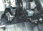
To AccuRounds' credit, because the idea ran counter to the company's preference for distributing the machining operations for a part among various machines in a cell, it began looking into CNC multi-axis lathes with live tooling, capable of performing all of the turning and milling operations required for the part in one setup. The company had some good reasons for looking at the more sophisticated machines. In the first place, AccuRounds was becoming more involved in just-in-time part-supply arrangements with customers, and the multi-axis lathes promised faster turnaround times on at least some jobs. Secondly, because of the shortage of skilled operators in the Boston area, the company was constantly faced with the problem of finding enough qualified workers to staff its machining cells. The multi-axis lathes offered a way around the labor-scarcity situation.
Easy Decisions
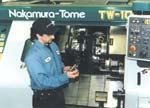
Star CNC Swiss screw machines and Nakamura-Tome CNC lathes have formed the backbone of AccuRounds' machining operation for years. It was only natural then, when the time came to step up to multi-axis lathes, that the firm bought a Model SV-32J Swiss screw machine from Star and a Model TW-10 CNC turn/mill machine from Nakamura-Tome. Finding the CAM software for its brand new machines was not so straightforward, however.
"We contacted the firm that supplied the CAM software we use for off-line programming of our conventional CNC lathes and mills and asked if they had a product for our new multi-axis lathes," recalls Mr. Martell. "They said they were looking into it and would have something in the near future—but couldn't give us a time frame." He also approached several of the software firms that he had talked to in the process of choosing his original CAD/CAM program, with much the same results.
Mr. Martell, who is also head programmer for AccuRounds, resigned himself to programming each of the new machines at its CNC control until he could find a suitable off-line CAM package. Finally, AccuRounds president Michael Tamasi heard about PartMaker CAM software made by Delcam and asked Mr. Martell to look into it. Mr. Martell learned IMCS not only had a CAM program suitable for AccuRounds' turn/mill machine, but it also had one for its CNC Swiss screw machine. After a demonstration of the program, AccuRounds purchased the PartMaker Suite.
PartMaker is an off-line CAM programming software developed specifically for multi-axis lathes with live tooling. It is a visual programming system that operates from graphical representations of the various faces of the part.
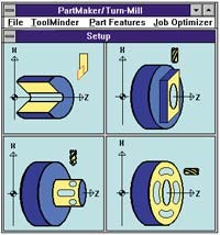
The system breaks the surfaces of the part into a set of faces. The faces can be planar or rotational, and each can contain various machined features such as slots or holes, as is shown on page 85. A specific machining function such as turning, polar milling or cylinder milling is assigned to each face. A dedicated window, referred to as a face window, contains a workspace for the graphical representation of the face features. Specific milling capabilities of the multi-axis lathe determine the selection of faces. For example, Y-axis programming is not represented unless the machine is so equipped.
A dialogue box associated with each face window contains a pictorial representation of the machining operation to be performed, the location of the face boundaries, and the positioning of the face relative to the machine coordinate system.
The software includes an integrated tool database that contains data for each of the tools used on the machine tool being programmed. A dialogue box is associated with each type of tool (drills, end mills and so on). A graphic representation of each tool type and a list of each tool's parameters are also provided. Once the tool data is entered, it is permanently stored in the database for the life of the tool.
For repetitive operations such as center drilling, drilling, tapping, boring, chamfering and so on, the programmer needs only to create the cycle one time. The cycle can then be stored in a cycles database, which is linked to the tools database. The graphical user interface makes creation and modification of cycles a simple task.
The software comes with an extensive materials database, with recommendations for average cutting parameters. Feed rate and spindle speed are computed based on tool geometry (size, number of flutes and so on) and machineability data.
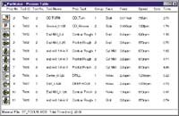
Rather than create a job plan in a conventional sequential manner, the programmer describes the placement of groups of part features on the surfaces of the machined part. Once the part feature description is entered into the computer, the software automatically generates an optimized job plan. The results of the job plan are summarized in a process table window, as is shown below. The table lists tools and cutting conditions for each process. Feed rates, spindle speeds and cycle time are automatically calculated and displayed. The cycle time allows the programmer to quickly estimate the time and cost of machining the part.
When the programmer is satisfied with the views of the part and its job plan, he or she can proceed to the next step, postprocessing to automatically generate an NC program for a particular multi-axis lathe. Multiple programs with synchronization points are generated for turn/mill centers that require a separate program for each set of programmable axes. The software eliminates any need to manually edit the generated NC program.
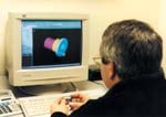
In order to validate the correctness of the CNC program, the NC code verifier reads, interprets and executes each line of the part program. A 3D solid model simulator (page 82) reproduces the cutting tools' movements to demonstrate on screen the process of material removal and the shaping of the workpiece into a machined part.
Halves Programming Time
Before AccuRounds acquired the PartMaker programming system, Mr. Martell programmed the new multi-axis lathes right at the machine. "Programming of a complicated part at the machine would take 3 1/2 to 4 hours," he recalls. "Working with PartMaker at a PC in the engineering office, I can program the part in 2 hours. That includes creating a CAD drawing of the part from the customer's blueprint. If the customer provides the CAD file, I can prepare the NC program in about 1 1/2 hours."
Mr. Martell found the program very easy to use once he learned his way around the windows. And he also learned to appreciate a number of the software's features. For example, when the shop runs a job on a mill/turn or CNC Swiss lathe for the first time, it is very concerned about avoiding interferences. The software incorporates an "NC verify" feature, a graphic that simulates the movement of the various tools in the machining of the part. Any collisions or interferences are flagged in red. "I just go back and look for the mistake, correct it, and reverify the program. It's a 10-second fix," he notes.
Flexible Too
Although the software brings a valuable consistency to multi-axis turned part programming, it still provides a high degree of programming flexibility. This is probably best demonstrated by the fact that the operations need not be programmed in the order they will be performed on the machine. They can be handled in the order most convenient to the programmer and arranged in the proper sequence afterwards.
The flexibility of the program is pervasive, extending even to such things as to tool positioning considerations. For example, Mr. Martell can specify how he wants the tool to approach the part for a particular operation, its angle, how it exits the cut and so forth. And although cutting speeds and feeds for the various cuts are automatically calculated using data from the program's materials and tool libraries, the programmer or operator can easily "tweak" the numbers to optimize cutting conditions.
Before Mr. Martell began using PartMaker to program the shop's multi-axis lathe parts, he had a steady backlog of 20 jobs. Now, the backlog has all but disappeared, and part programming is no longer a factor in job turnaround time at AccuRounds. That's important because the programming of multi-axis lathe parts is expected to increase in the near future.
Currently, 10 to 15 percent of AccuRounds' new jobs go on the multi-axis lathes, and the number will be going up. "Every machine that we've purchased recently has multi-axis machining capability," Mr. Tamasi emphasizes. "Of our remaining CNC turning machines, only four are not multi-axis machines. We have two more multi-axis lathes coming in beginning next week. As we add more such machines, more of our parts will be processed on them. That will enable us to provide our customers with shorter lead times and improved part-to-part consistency.
"When we tried to use our original software to program our new multi-axis machines, we just were unable to get the postprocessed programs written properly for the machines," Mr. Tamasi continues. "We weren't able to get a complete program from our existing CAM package. It wasn't sophisticated enough to handle our new-age machines. PartMaker has gotten us over that problem, and just as the new machines are enabling us to produce more and more complex parts in less time, our new software is enabling us to program those parts in less time."
Related Content
Can AI Replace Programmers? Writers Face a Similar Question
The answer is the same in both cases. Artificial intelligence performs sophisticated tasks, but falls short of delivering on the fullness of what the work entails.
Read MoreCan ChatGPT Create Usable G-Code Programs?
Since its debut in late 2022, ChatGPT has been used in many situations, from writing stories to writing code, including G-code. But is it useful to shops? We asked a CAM expert for his thoughts.
Read MoreHow this Job Shop Grew Capacity Without Expanding Footprint
This shop relies on digital solutions to grow their manufacturing business. With this approach, W.A. Pfeiffer has achieved seamless end-to-end connectivity, shorter lead times and increased throughput.
Read More5 Tips for Running a Profitable Aerospace Shop
Aerospace machining is a demanding and competitive sector of manufacturing, but this shop demonstrates five ways to find aerospace success.
Read MoreRead Next
Building Out a Foundation for Student Machinists
Autodesk and Haas have teamed up to produce an introductory course for students that covers the basics of CAD, CAM and CNC while providing them with a portfolio part.
Read MoreSetting Up the Building Blocks for a Digital Factory
Woodward Inc. spent over a year developing an API to connect machines to its digital factory. Caron Engineering’s MiConnect has cut most of this process while also granting the shop greater access to machine information.
Read MoreRegistration Now Open for the Precision Machining Technology Show (PMTS) 2025
The precision machining industry’s premier event returns to Cleveland, OH, April 1-3.
Read More


