Making Programming Hands-Free (Almost)
Feature-recognition CAM software helps this technology company's internal mold shop deliver critical molds more quickly. A programmer is still needed, but the software automation saves considerable time.
Share


Changes that address the leadtime required to make a mold tend to focus on the machining cycle. A faster machine following suitable tool paths can allow machining cycles for cores and cavities to proceed considerably faster. However, saving time from these cycles can only go so far; significant time is also lost elsewhere. Making a mold demands not just machining time, but also programming time—and much of that programming may not even involve the core and cavity.
For a small mold shop within Rockwell Automation, the response time for delivering a mold has steadily become more critical. The shop occupies the fifth floor of the Milwaukee, Wisconsin, headquarters for Rockwell’s Allen-Bradley brand. As the company has become steadily more proficient at outsourcing mold making to suppliers, the mission of this shop has changed. Jobs that remain in-house include molds that are difficult to outsource—along with molds that are just plain difficult. Among the shop’s time-critical work are the repair and replacement jobs for molds that are needed urgently, because the production of some plastic component is being delayed for want of that mold.
Jeff Wendtlandt is a senior mold build technician with this shop. He both programs machining work and oversees that work at the machining center. Delivering molds quickly used to be far more difficult for the shop, he says, and the reason had more to do with programming than it had to do with machining.
Mold assembly designs used to arrive as wireframe CAD models, he says. The programmer would study prints to isolate the distinct features of the various machined parts that make up the mold. Later, the use of wireframes was replaced by solid models, allowing bases, plates and other mold components to be represented as separate solids. Models were easier to view and comprehend downstream. Even more significantly, however, the move to solid models made it possible for CAM software to make better use of the models. Using a CAM system capable of feature recognition and knowledge-based machining, the Rockwell shop has now automated much of the redundant programming work that used to take so much time.
Deceptively Simple
Mold bases and plates are rectangular parts that are relatively simple to machine. The work they require is generally 2D instead of 3D, consisting mostly of holes and pockets oriented along the same axis.
However, the work that these features require of the programmer is more complex. Any base or plate might include a lot of these features—a lot of holes in particular. Any of the holes might require a series of tools for operations including centering, drilling, reaming, tapping, countersinking or counterboring. The programmer therefore may have to recognize the nature and purpose of every hole, recognize the machining requirements of every hole to achieve this identity, think through the tools based on these requirements, then select the right tool numbers for the hole out of the shop’s standard tooling. When multiplied by all of the features of the various components of the mold, applying this thinking to each feature can result in significant programming time.
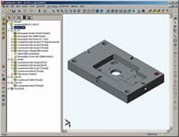
But now that thinking has been automated. The shop programs base and plate machining using CAMWorks software from TekSoft (Scottsdale, Arizona). CAMWorks uses feature recognition algorithms to identify machined features of a part model automatically, and it uses a database of user-specified tools, toolpath preferences and assignment rules in order to generate a machining routine for each of the features it finds. While Mr. Wendtlandt still has to oversee the programming with this software, the time he saves is considerable. A mold that used to take 2 weeks for him to program now takes 2 days.
Input As Needed
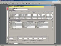
The software automation was productive almost immediately for the Rockwell shop. One fear about implementing a knowledge-based system is that the effort of inputting a shop’s “knowledge” will represent a time-consuming initial hurdle. Mr. Wendtlandt did not experience this problem. In the beginning, the software’s default machining rules were close enough to his needs, he says. He modified the rules for assigning and creating machining routines only where a default rule was clearly inconsistent with the shop’s preferred techniques, or inconsistent with its knowledge of what the machine can do. Mr. Wendtlandt also input data about the shop’s preferred cutting tools only as those tools were needed. To do just this much work did not take him any more time than what he would have spent to program a base or plate using the previous approach.
On the shop floor, Mr. Wendtlandt watches how the cycle progresses. In each place where one of the automatically generated cycles is visibly inefficient, he makes a note to himself to modify the rules in the database that produced that particular routine. This monitoring, too, does not take extra time, because learning from experience and making notes for future reference has always been part of his work. The difference now is that he has a single, reliable place to input what he learns, so that the best practices he develops will consistently be applied whether he remembers his own notes or not.
Over time, this process of encountering slow spots in machining cycles and tweaking the database has produced a knowledge-based system that departs significantly from those early default parameters. The system is now tailored to the way the Rockwell shop and Mr. Wendtlandt want to machine. In fact, Mr. Wendtlandt’s dual role of both programming and running the machine has made him particularly effective at refining the software’s knowledge in this way, because he sees immediately when something about the program is not performing the way he intended. Maybe a feed rate can be increased; maybe a tool cuts air a little too long; or maybe a given drill should penetrate just little farther out of the hole. Tweaks such as these generally can’t be seen in the software’s rendering of the cycle, but they sometimes become obvious when the program is actually cutting metal.
The Counterbore As Clue
While the software’s automatic feature recognition responds to geometry, it doesn’t necessarily respond to intent. This is why a programmer such as Mr. Wendtlandt is still needed for each job.
A hole, for example, might be a spring hole, a hole for a support, an ejector pin hole or a screw hole (among other hole types). Chamfers might be different for the different hole types, and holes may or may not be threaded—details which may or may not be clear or accurate in the model.
Similarly, an open pocket in a mold might exist for the sake of a slide or a parting line lock. Mr. Wendtlandt machines these two different types of pockets in different ways—another case where the software could not be expected to recognize the distinction. When the software tries to identify features such as these, Mr. Wendtlandt generally has to correct the identifications.
The software makes the correction interactive and easy. For a given model, the software presents a list of the features it identified, and Mr. Wendtlandt clicks through the list quickly to make different identifications. Once the features have been correctly named in this way, the correct tools and tool paths are assigned to the features automatically, and the complete NC program is built up from these choices.
Mr. Wendtlandt continues to make the process even more automated. He has recently begun using the geometry the software sees to indicate the type of hole and the tool that should be used to machine it. A “cheat sheet” he developed for designers lists his requested counterbore sizes for various screw holes and ejector holes. According to his rules, for example, a size-8 screw hole should have a 0.297-inch counterbore diameter, while a 5/32-inch ejector pin hole should have a counterbore diameter of 0.2968 inch. The difference of 0.0002 inch between the two counterbore sizes may be meaningless to the functioning of the holes, but those different diameters will cause different counterboring tools to be selected in the database rules Mr. Wendtlandt has set up. This is significant, because the ejector pin hole requires a chamfer that the screw hole should not have. With counterbore diameters providing the clue in this way, the software can be trusted to identify the hole type and select the right tool without the need for a human being to correct the choice.
Specific Features
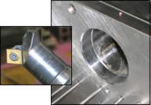
The system also gets steadily better as Mr. Wendtlandt adds more rules to the database that address more specific features. A recent example involved the use of a milling tool from Kennametal that is able to chamfer both the entry and the exit of certain holes. (See photo.) In order to apply this tool automatically, Mr. Wendtlandt worked out how far the tool must penetrate into the hole to let one insert edge chamfer the entry (0.100 inch), and how far past hole the tool has to extend to let another insert edge chamfer the exit (0.350 inch). He also identified the minimum hole diameter and maximum workpiece thickness this tool can accommodate. Armed with all of this information, he was able to devise the rules governing both when and how this tool should be applied. As a result, he no longer even has to remember that he has this specialized tool in his arsenal. Like every other tool in the database, this one will now be applied automatically, whenever the pre-existing rules suggest that the use of this tool makes sense.
Related Content
Four-Axis Horizontal Machining Doubles Shop’s Productivity
Horizontal four-axis machining enabled McKenzie CNC to cut operations and cycle times for its high-mix, high-repeat work — more than doubling its throughput.
Read MoreHow to Accelerate Robotic Deburring & Automated Material Removal
Pairing automation with air-driven motors that push cutting tool speeds up to 65,000 RPM with no duty cycle can dramatically improve throughput and improve finishing.
Read MoreWhich Approach to Automation Fits Your CNC Machine Tool?
Choosing the right automation to pair with a CNC machine tool cell means weighing various factors, as this fabrication business has learned well.
Read MoreSame Headcount, Double the Sales: Successful Job Shop Automation
Doubling sales requires more than just robots. Pro Products’ staff works in tandem with robots, performing inspection and other value-added activities.
Read MoreRead Next
5 Rules of Thumb for Buying CNC Machine Tools
Use these tips to carefully plan your machine tool purchases and to avoid regretting your decision later.
Read MoreSetting Up the Building Blocks for a Digital Factory
Woodward Inc. spent over a year developing an API to connect machines to its digital factory. Caron Engineering’s MiConnect has cut most of this process while also granting the shop greater access to machine information.
Read MoreBuilding Out a Foundation for Student Machinists
Autodesk and Haas have teamed up to produce an introductory course for students that covers the basics of CAD, CAM and CNC while providing them with a portfolio part.
Read More


