It's Within Your Grasp -- It Will Extend Your Reach
Though high speed machining means different things to different people, all of the diverse applications of this process involve performing operations fast enough to break into a new realm of possibilities.
Share


Hwacheon Machinery America, Inc.
Featured Content
View More


Takumi USA
Featured Content
View More
The push toward high speed machining is coming from three key areas: mold and die, aerospace, and automotive. Each of these industries is motivated by different interests and goals; each is emphasizing different technologies to solve divergent problems; each faces different challenges in regard to the workpiece materials and lot sizes. This makes it difficult to define high speed machining.
Numbers given for speeds, feeds and other machining parameters are helpful for characterizing the process but they tell only part of the story. What's considered high speed machining in one industry is not the same in another. And the numbers keep changing. They keep going higher and higher all the time, it seems.
Even the term "high speed machining" is not universally accepted, although it is the most widely used expression. Many prefer the term "high velocity machining." This term distinguishes the breakthrough happening today from yesterday's efforts to reach the next increment in machine performance (we've been talking about high speed machining of this sort for the last 20 years).
The term high velocity machining also implies that this process involves more than high spindle speeds. To some observers, high feed rates, high rapid traverse rates, high acceleration and deceleration rates, and fast tool change times are part of the high speed machining formula. And no matter which one of these parameters you choose to talk about, the qualifier "high" is entirely relative. Feeds of 100 ipm raise eyebrows in some discussions. In others, anything less than 1,000 ipm is ho-hum.
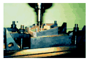
A better way to define high speed machining is to say that it covers a number of metal removal processes that exceed the point beyond which desirable but otherwise unattainable results can be reached. It is easy to identify these general departure points without using hard numbers as the deciding factor. For example, in the mold and die world, high speed machining allows the trade-off between time on the machine and time on the polishing bench to shift dramatically—a little more time on the machine means a whole lot less time on the bench. See Figure 1 at right. The point where this shift begins to occur marks one of the boundaries of high speed machining. (This shift often yields a double bonus—high speed machining often reduces total machining time as well as reduces or eliminates bench time.)
Similar thresholds exist in other industries. When does it become more attractive to mill that landing gear strut from the solid rather than from a casting? When does it become possible to machine extremely thin walls in delicate materials? When does it become more attractive to use CNC machining centers rather than dedicated transfer lines on those aluminum carburetor bodies? Those questions give better answers than picking numbers.
Everything Changes
We pointed out earlier that high speed machining represents the convergence of several technologies. On one hand, some of these technologies converge in the machine tool itself. Innovative or advanced components such as the spindle, axis drive motors, feedback sensors, control unit, and so on, work together with a synergistic effect. Cutting forces drop, surface finishes feel like glass, cycle times plummet.
On the other hand, some of those technologies must converge around the machine tool. High speed machining almost always involves some modifications to a shop's infrastructure. For example, NC programs for high speed machining of dies may include huge amounts of data—ten megabytes is not uncommon. An Ethernet network may be required to download programs of this size efficiently.
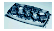
Likewise, high speed machining may call for adjustments in a plant's "work culture." In a mold shop, for example, high speed machining of graphite electrodes (Figure 2, at left) has a major impact on EDMing, making it much more efficient in terms of fewer "burns" and/or shorter "burn times." But job planning, work scheduling, and coordination between departments has to be handled much more carefully to exploit these benefits.
Safety is another issue that will make shops to do things differently to do high speed machining. The potential energy involved in high speed machining is naturally higher, so extra precautions need to be followed at almost every step. For every element of a high speed machining system, diligent and prompt maintenance procedures must followed scrupulously.
When modifications to shop infrastructure are in place and adjustments to work culture have been made, there should be a synergistic effect not unlike the synergy that results from the interaction of advanced machine tool components. Business grows; profits rise; morale soars. But maintaining this synergy is a management challenge that rivals if not surpasses the technical challenges of high speed machining. Establishing new disciplines and new responsibilities in the workforce calls for superior leadership and above-average people skills. These abilities will never be available for purchase like items off the shelf.
Looking at the experiences of companies that have adopted high speed machining shows that a common path has been to proceed from bottleneck to bottleneck, or from barrier to barrier. Opening a bottleneck in one area creates another somewhere else, either upstream or down. That new bottleneck then becomes the focus of attention. For example, high speed machining "eats up a lot of programming," as one shop manager put it. Restructuring the programming department was this next step.
Likewise, breaking a technical barrier in one process variable (such as spindle speed) typically leads to new barriers in other process variables (such as balance of the tool and toolholder assembly) that must be overcome. Some shops that were never concerned about balancing tools and toolholders are now investing in tool balancers once they encounter spindle speeds surpassing 15,000 rpm, for example.
This is why high speed machining is finally coming into its own. Machining had been boxed in by walls of dovetailed constraints but now we are able to knock out all the corners at once.
Aluminum For Airplanes
One of the most striking examples of converging technology creating this sort of breakthrough can be seen in high speed machining for the aerospace industry.
There is a point where machining at very high surface footage exhibits a significant reduction in cutting forces and power consumption while at the same time causing heat to transfer mostly into the chip rather than into the cutter. In aluminum, this effect appears when surface footage reaches 5,000 or higher, according to one well-experienced practitioner. This is a substantial benefit when machining thin-walled aluminum aircraft components, one of the most important high speed machining applications in this industry.
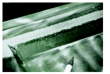
These components must be light but stiff. Typical parts feature numerous pockets; the walls between the pockets serve as stiffeners. These parts are often very long relative to width and are typically machined from solid slabs of aluminum alloy. High speed machining has two main values. The obvious one is high metal removal rates: "Hogging out" a lot of material in as little time as possible is a key factor in productivity. However, the ability to machine thin walls—thinner than would be possible using conventional techniques—is a real breakthrough because it permits parts to be designed with a lower weight to stiffness ratio. The test piece shown in Figure 3 (at right) is a good example of the thin walls commonly encountered in this application. More important, it makes it economically feasible to replace parts assembled out of sheet metal with monolithic parts machined from a single billet of raw material. Monolithic parts tend to be stronger, lighter, and cheaper. Finished component parts do not need to be inventoried. Only the corresponding machining program needs to be archived for reproducing a replacement part on command.
The "secret" is machining these walls at parameters that exceed those which normally induce vibration and result in chatter. At adequately high surface speeds, cutting forces go down significantly. Specifically, side forces are reduced to the point that they have a negligible influence on deflection of side wall material.
High speed machining of aluminum is important outside the aerospace industry as well. The automotive industry is forecasting a dramatic increase in the use of aluminum for major powertrain components, for example. Likewise, the mold and die industry is making greater use of aluminum for prototype tooling. These opportunities for the machining of aluminum will get many new users started in high speed technology.
Flexible Modules
High speed machining represents a major shift in processing strategies and opportunities for the production of high-volume parts in the automotive industry and this development deserves special attention. Although increasing use of aluminum in automotive components is one key underlying reason, cast iron applications are beginning to show up more frequently as well.
Making a lot of parts as quickly as possible in order to reduce costs has been a long standing objective in the automotive world. And it has always taken two approaches, usually at the same time: minimize non-cutting time (tool changes, moves between cuts) and maximize metal removal operations.
High speed machining centers used as flexible modules in a production line is the most common implementation of this tactic. They are an alternative to the hard automation of the conventional transfer line. High speed machining is, in fact, the element that changes the economic formula in favor of the flexible modules, because it allows these machines to approach, even surpass, the cycle times attainable on transfer lines. At that point, the flexibility of the modules becomes the deciding factor. These machining centers can be retooled, reprogrammed, and rearranged to meet new production assignments.
These flexible modules are fast on two fronts. Spindle speeds and feed rates match those of the high speed machines sculpting mold cavities or buzzing through a wing spar. Ingersoll's HVM 600, a classic example of this breed of machining center, has a 20,000-rpm spindle with a 50-hp drive motor, axis acceleration of 1.5 G, and top feed/rapid traverse rates of 3,000 ipm.
The other front that these flexible modules have to be fast on is non-cutting functions. Many automotive parts require a succession of drilling, boring, reaming, and tapping operations on five or six sides of the workpiece. So tool change time, pallet changing or indexing, and rapid traverse rates are critical. The VMCs from Chiron America (Charlotte, North Carolina) for example, change tools in 0.55 second, index the pallet in 2.0 seconds, and have top rapid traverse rates of 2400 ipm. However, as you can see, machine tool builders face diminishing returns on this front. There's precious little slack left to wring out of these motions. Further increases in metal removal rates, however, still offer gains worth pursuing.
Molds And Dies
In mold and die work, the essence of high speed machining is making a lot of passes at very small stepovers at very high feed rates in tool steels. This strategy works for both roughing and finishing operations. In roughing operations, a smaller depth of cut using positive rake cutters often achieves higher overall metal removal rates, even though the cutting tool is of a smaller diameter, compared to typical roughing operations involving fewer, slower, heavier cuts. Tool life also improves. In many cases, high speed roughing takes the workpiece close enough to the stock allowed for finishing that a semi-finishing operation can be eliminated.
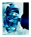
Eliminating operations is also the goal for finishing passes at high speed, but in this case, operations after machining are the ones to be eliminated or reduced. Smaller cuts taken closer together result in an inherently smoother surface. Typically, stepovers may be as little as 0.001 inch, leaving cusps only 0.00005 high. On many workpieces, the surface quality may be so fine that little or no benchwork is required. See Figure 4, at left.
High speed makes the tradeoff between machining and benching attractive. By vastly increasing feed rates during finishing operations, the stepover from pass to pass can be greatly reduced without adding excessive machining time. Eliminating or reducing subsequent polishing or grinding at the bench preserves the as-machined surface.
So what do you need for high speed machining of tool steel in a mold or die shop? Ron Field, an application engineer at Makino (Mason, Ohio), one of the machine tool builders that has prominently promoted high speed mold and die machining, likes to emphasis the practicality of the process in his answer. To win the benefits of high speed machining, you need a machine tool capable of achieving at least 1200 surface feet per minute (sfm), which is going to require a minimum of 8,000 rpm from the spindle, he points out.
A high speed spindle can be retrofit to an older machine tool to achieve these speeds, although the overall stability of the machine may be a limiting factor. However, a number of machine tool builders are now offering machining centers specifically designed for high speed machining, with superior stiffness being one of their principal characteristics.
According to Mr. Field, the tooling required for high speed machining is not much different than the tooling needed for traditional machining. He recommends Cermet or TiCN-coated insert tooling or solid carbide with TiN or TiCN coatings for steels under 40 Rc. For harder materials, solid carbide with TiAIN coating, or CBN, are the tools of choice. In his experience, some very hard materials actually machine better at high speed, D2 die steel hardened to 50 Rc, for example.
Regardless of the cutting tool material, it is very important to make sure the cutting tool and toolholder assembly are sufficiently balanced for the speeds at which the spindle will be turning. Otherwise, excessive vibration will lead to runout problems, lower tool life, poorer surface finish, and less than optimal accuracy.
If the process is not sufficiently balanced with standard tools, there are options for making the balance better, Mr. Field notes. Shrink fit toolholders are best but special equipment is required. A hydraulic tool-holding chuck is a good second choice. All of the major cutting tool and toolholder manufacturers, however, are responding to the demand for balanced or balancable tooling, and prices are coming down. The bottom line is, the need for balanced tools is a cost item but the investment is clearly worthwhile.
When it comes to the impact high speed machining has on shop infrastructure, mold and die shops typically undergo more reshaping than any other industry with a stake in high speed machining. That's due to three additional ingredients in the recipe for this process: preparing the mold's complex NC program, downloading it, and executing it.
NC programming, whether off-line or on the shop floor, is mostly a matter of using techniques already available in today's 3D CAM software. Roughing is governed by an interest in efficient metal removal while machining close enough to the finish stock allowances that a semi-finish pass can be reduced or eliminated. Finishing, of course, is governed by an interest in achieving a surface fine enough that benchwork can be reduced or eliminated while obtaining the best dimensional accuracy. In both operations, using smaller cutters and more closely spaced stepovers means more cutter passes.
For the finish cut, tolerances for chordal deviation must be set very low. (Mr. Field says they should be set under 0.0005 inch and even as low as 0.00005 inch.) Movement per block will be much shorter for better accuracy but the NC program will be considerably longer.
Downloading massive NC programs to the machine tool control unit is likely to be too slow if attempted with typical drip-feed DNC links. Upgrading the DNC system for higher transmission speeds (baud rates) is one option but installing a network with links to communications cards installed in the CNC is a better long-term fix. Adding a hard drive directly linked to the high speed bus used for internal data communication within the CNC is also recommended. This arrangement solves three potential problems. Transmitting the program from the CAM system or file server will be extremely quick. The entire program can be stored on the hard drive. Finally, the speed at which the program data is made available to the tool path processor will not be a limiting factor.
Executing the program is another matter. To machine accurate contours at high speed requires a fast and powerful control unit. It has to be capable of processing the blocks of data fast enough to keep up with the programmed feed rate. Look-ahead features allow the CNC to scan upcoming lines of code to detect abrupt changes in tool path direction and automatically adjust the feed rate. That give servos enough time to accelerate and decelerate to stay on path, but gentle curves and straight-aways can be cut at maximum speed.
Take It To The Customer
What all of these applications have in common is that high speed machining allows long-standing process barriers to be shattered. With these barriers removed, new production strategies become feasible. These new production strategies, in turn, allow companies to redirect their business strategies. In short, high speed machining makes it possible to serve customers differently—and better.
Ultimately, that is the goal of high speed machining. Serving customers better is also the final test of high speed machining. If you are doing high speed machining, or planning to, the effort has to be carried through to the point that your customers notice. They needn't be aware that this process is being applied to their benefit, but they should be aware of the benefits that are passed on to them: better design, higher quality, on-time or early delivery, reduced cost, greater flexibility, and so on.
In fact, high speed machining is likely to be a strong impetus for forging new ties with customers on several levels. High speed machining affects not only how parts are made, but also it affects how parts are designed and used. Without customer input and cooperation, these effects will be difficult to exploit fully. The customer's reward is sharing in the significant savings in cost and delivery time that high speed machining brings.
We're All Still Learning
There is no one right way to implement high speed machining. For one thing, the applications are extremely varied. It is hard to find more than broad generalities as a starting point. For another, shops with extensive experience in high speed machining admit that it takes time to develop a "feel" for what will work and how far they can go. It is not easy to convey that know-how in lessons for other users.
Shops that have not been afraid to experiment have learned the most. Most of these shops started with one machine, often an existing machine with a retrofit spindle. They have taken it one job at a time, relying heavily on whatever help they could get from tooling suppliers, machine tool builders, and dealers. They learned from setbacks and built on successes. Now they won't turn back.
Related Content
How to Successfully Adopt Five-Axis Machining
While there are many changes to adopt when moving to five-axis, they all compliment the overall goal of better parts through less operations.
Read MoreHigh RPM Spindles: 5 Advantages for 5-axis CNC Machines
Explore five crucial ways equipping 5-axis CNC machines with Air Turbine Spindles® can achieve the speeds necessary to overcome manufacturing challenges.
Read MoreHow to Determine the Currently Active Work Offset Number
Determining the currently active work offset number is practical when the program zero point is changing between workpieces in a production run.
Read MoreCNC Machine Shop Honored for Automation, Machine Monitoring
From cobots to machine monitoring, this Top Shop honoree shows that machining technology is about more than the machine tool.
Read MoreRead Next
5 Rules of Thumb for Buying CNC Machine Tools
Use these tips to carefully plan your machine tool purchases and to avoid regretting your decision later.
Read MoreSetting Up the Building Blocks for a Digital Factory
Woodward Inc. spent over a year developing an API to connect machines to its digital factory. Caron Engineering’s MiConnect has cut most of this process while also granting the shop greater access to machine information.
Read MoreRegistration Now Open for the Precision Machining Technology Show (PMTS) 2025
The precision machining industry’s premier event returns to Cleveland, OH, April 1-3.
Read More







.jpg;maxWidth=970;quality=90)