
How to Correctly Measure Surface Finish
When providing surface finish specs, engineers sometimes leave out the actual testing parameters. Here’s how to be sure measurements are as accurate as possible.

Share


Takumi USA
Featured Content
View More

.png;maxWidth=45;format=webp)
DMG MORI - Cincinnati
Featured Content
View More
When an engineer includes a surface finish spec on a print, the intent is usually not just to make the part look good. Surface finish affects how a part will fit, wear, reflect light, transmit heat, distribute lubrication and accept coatings. The finish should be determined by the part's function; ideally, the surface should fulfill the engineering requirements of the application without wasting time and effort on producing a higher quality finish than is necessary. In fact, many applications do better with a certain amount of “texture.” Too fine a finish can be as bad as too coarse.
Surface finish — also known as profile — includes two components: waviness and roughness. Waviness, or longer-wavelength variation, is caused by macro-type influences, such as worn spindle bearings or vibration from other equipment on the shop floor. Roughness is the short-wavelength pattern of tool marks from grinding, milling or other machining processes, and is affected by the condition and quality of the tooling. Both can be influenced by the operator's choice of feed rate and depth of cut.


Most surface finish checks are done on machined surfaces where a cutting tool has been run across a surface and the resulting tool marks create the profile. But there are other ways of creating a surface finish and it can be just as important to ensure that those resultant surfaces also meet their engineers’ design requirements. For example, surfaces can be created by grinding, polishing or grit-blasting, which may have requirements for specific peaks and valleys so the surface can be coated with specialized materials.
One problem that often occurs is that, while the engineer includes the surface finish spec on the print, the actual testing parameters are not included. Normally, Ra is used to measure the roughness of a surface; however, with any surface finish measuring device, there are numerous parameters that should be set to ensure the correct roughness measurement result.
Today, standards for surface finishing provide recommendations for what the surface finish result should be in addition to the appropriate measurement parameters, such as cutoff length. If these parameters are not specified, there is a strong likelihood of incorrect results from surface finish measurements.
Different types of surface manufacturing techniques are used to produce very different types of surfaces. The machining process, with its cutting tools, spindles and slides, tends to produce a “periodic” surface — one that shows a clear repeating profile; the tool marks are easily distinguished. On the other hand, grinding or grit-blasting produces a non-periodic surface — in other words, it does not have a repeating profile. Incorrect measurement setup can produce errors in either technique.
When measuring surface roughness, the first step is to filter out the waviness component from the roughness component. This is done by breaking the total measuring length of the surface finish measuring stroke into small segments, called cutoff length. Typically, the default cutoff length is set at 0.8 mm. When using this cutoff length on these types of surfaces, there is a chance that an incorrect roughness reading may result. Therefore, if no specified parameter setting for cutoff is called out on the part print, the surface standards define a procedure for selecting the correct cutoff for the surface.
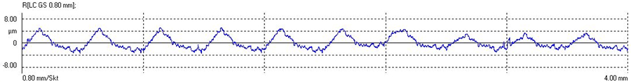
Periodic surfaces are characterized by equally spaced, recurring, typical profile characteristics that are clearly visible in both the depiction of the test surface as well as in the profile. Images courtesy of George Schuetz.
A table helps determine the proper cutoff according to the profile type, either periodic or non-periodic. It requires a bit of experimentation, but it is worth the effort to achieve the proper test results.
Once the type of surface is determined (periodic or non-periodic), columns in the table guide to the proper cutoff setting. If the surface is periodic, the Rsm mean width of the roughness profile elements is used to indicate the correct cutoff length. First, determine the profile length and the chart will recommend a cutoff length. If another measurement produces a result where the Rsm and cutoff length agree, then the Ra is apt to be correct.
On the other hand, if the surface is non-periodic, the table makes a cutoff length recommendation based on the measured Ra. A number of measurements are then made to find the best match of Ra and cutoff length. This is a bit of a tedious process but one that goes a long way to ensure the best surface roughness result.
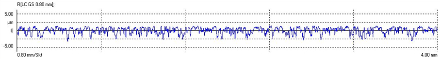
Non-periodic profiles do not show any visually striking special surface or a distinct working direction on the surface.
Of course, it’s a lot easier when the engineer includes all the setup parameters on the surface callout, but if not, there is a way to ensure the best potential setup and results in the surface standards.


Related Content

The Many Ways of Measuring Thickness
While it may seem to be a straightforward check, there are many approaches to measuring thickness that are determined by the requirements of the part.
Read More
6 Machine Shop Essentials to Stay Competitive
If you want to streamline production and be competitive in the industry, you will need far more than a standard three-axis CNC mill or two-axis CNC lathe and a few measuring tools.
Read More
Turning Fixed-Body Plug Gages Inside Out
Fixed-body mechanical plug gages provide fast, high-performance measurement for tight-tolerance holes.
Read More
Help Operators Understand Sizing Adjustments
Even when CNCs are equipped with automatic post-process gaging systems, there are always a few important adjustments that must be done manually. Don’t take operators understanding these adjustments for granted.
Read MoreRead Next

5 Rules of Thumb for Buying CNC Machine Tools
Use these tips to carefully plan your machine tool purchases and to avoid regretting your decision later.
Read More
Building Out a Foundation for Student Machinists
Autodesk and Haas have teamed up to produce an introductory course for students that covers the basics of CAD, CAM and CNC while providing them with a portfolio part.
Read More
Registration Now Open for the Precision Machining Technology Show (PMTS) 2025
The precision machining industry’s premier event returns to Cleveland, OH, April 1-3.
Read More