How Prototyping Addresses Unknowns and Reduces Risks
One benefit of metal AM is the capability to create functional prototypes in less time, enabling you to rapidly iterate on design alternatives during development.
Share


Regardless of whether you are trying to save cost, minimize mass or maximize performance with additive manufacturing (AM), you will invariably face new unknowns and uncertainties, which translate into new risks. AM is still an infant compared to machining, forging and casting, the elder statesman of manufacturing.
Recall that 3D Systems introduced the first AM technology to the market (a process now referred to as vat photopolymerization) just over three decades ago, and metal AM systems have only been commercially available since the mid-2000s; so, it should not be a surprise that there are still so many unknowns and uncertainties with AM. These unknowns and uncertainties create new risks.
How are people handling AM risks in the industry? Well, the U.S. (along with many other countries) have collectively poured many millions of dollars, if not a few billion, into research and development to understand the complex physics, heat transfer and materials science in AM processes, particularly laser powder bed fusion. This is essential to understanding the process-structure-property relationships that drive the performance, durability and useful life of the resulting parts made with AM. If that is understood, then we can control the AM process to achieve the material microstructures that we need to get the mechanical properties that we want to meet the requirements that have been set for the part. Sounds easy, but it is not.
If you find yourself uncertain about how an AM part will build or perform and you don’t have millions of dollars (or lots of time) to invest to figure it out, what do you do? Well, if you can’t find a solution documented in a report or a paper, and if other companies are not willing to share that information with you (because they have invested millions to mitigate the risk, giving them a competitive advantage), then you do what we have been doing since 3D printing hit the market: you prototype, but this time, you do it more intelligently and you do it fast.
One of the benefits of metal AM is the capability to create functional prototypes in less time, enabling you to rapidly iterate on design alternatives during development. Meanwhile, because AM is a digital process that does not require any tooling (beyond a build plate or platform), it makes no difference whether you are printing the entire part or just a sample or section of the part to test. In fact, you can even print variations of a single feature on a part and run tests to see what prints best, thus reducing the risk associated with that unknown.
Combining these three aspects together, we do what I refer to as Rapid Intelligent Prototyping, or R.I.P. — a cost-efficient and effective approach to address unknowns and reduce risks with AM. The approach is by no means new or unique, and nearly every company that I have worked with does some form of this, albeit under different names. In fact, it seems that anyone using AM, particularly metal AM, eventually comes to the same conclusion as users try to maximize learning at minimal cost.
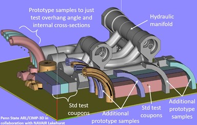
The extra space on a build plate can be used to print small samples and variations to address unknowns or associated risks with a metal AM part made using laser powder bed fusion. Photo Credit: Penn State CIMP-3D
We naturally started doing this on some of our early AM projects a decade ago. We were trying to understand how the overhang angle and internal cross-section of a hollow metal tube influenced the internal and external surface roughness, which might impact the flow in the AM hydraulic manifold we were helping to develop. As a result, we simply printed several small sample prototypes with slight variations on that specific geometry (see Figure 1) so that we could take measurements on the as-built and post-processed surface roughness.
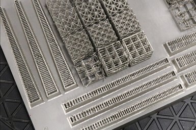
Our thinking has gotten more creative and sophisticated over the years, but I am still learning. In fact, we were recently building some small lattices, printing small 3 × 3 cubes (versus the full-size structure) in various materials and configurations to examine the printability of unsupported horizontal struts of different lengths and thicknesses. Eventually we realized that we did not need to print the whole 3 × 3 cube, let alone a unit cell; we simply needed to print horizontal struts of varying lengths and cross-section thicknesses to answer our question. This turned into little, xylophone-like structures that could be visually inspected for failure and easily measured while on the build plate (see Figure 2). I still remember smacking myself in the head two or three builds into our testing when I realized that we were “over-printing” for our experiments — we weren’t quite as rapid or as intelligent as we could have been!
Anyone doing process parameter development takes a similar approach. Don’t try and print the whole part while varying process parameters and toolpaths; rather, start with simple lines and layers before working up to cubes and more complex geometries. There is no sense building a small cube, for instance, if you can’t get a good layer, and you will never get a good layer if you cannot lay down a good bead/track in the first place.
Over the years, I have seen countless examples of small prototypes, sample parts or feature variation studies printed in the “extra space” on a build plate like we did early on with our hydraulic manifold. These are different from the witness coupons, tensile bars and other test coupons that are necessary for quality assurance and control. We still need those, too, but in the early stages of new product development, the uncertainty and unknowns are often closely linked to printable geometry since detailed design guidelines are not ubiquitous yet.
Most people probably do some form or another of this already. For others, this is yet another reminder to think differently when it comes to AM — not only about what can be designed and manufactured, but also about how to design and develop a part from the start. Then, when users uncover some unknown or have a question on what will (or will not) print, they can be smart and say R.I.P. to the AM risk.
Related Content
The Benefits of Vertically Integrating Metal 3D Printing and Machining
Having 3D printing and machining within one organization enables Addman’s engineers to collaborate and consolidate so it can quickly make successful metal 3D printed parts.
Read MoreA Fond Farewell to My Additive Friends
In his final “Additive Insights” column, Tim Simpson reflects on how additive manufacturing has progressed in the last six years. Standards and software are two examples.
Read MoreDigitalization and Done-In-One Reign Supreme at BIEMH 2024
European manufacturers may have a different balance of markets than their U.S. counterparts, but the practical challenges they must overcome are often similar — as are the solutions.
Read MoreMachine Tool Drawbar Made With Additive Manufacturing Saves DMG MORI 90% Lead Time and 67% CO2 Emission
A new production process for the multimetal drawbar replaces an outsourced plating step with directed energy deposition, performing this DED along with roughing, finishing and grinding on a single machine.
Read MoreRead Next
Building Out a Foundation for Student Machinists
Autodesk and Haas have teamed up to produce an introductory course for students that covers the basics of CAD, CAM and CNC while providing them with a portfolio part.
Read MoreSetting Up the Building Blocks for a Digital Factory
Woodward Inc. spent over a year developing an API to connect machines to its digital factory. Caron Engineering’s MiConnect has cut most of this process while also granting the shop greater access to machine information.
Read MoreRegistration Now Open for the Precision Machining Technology Show (PMTS) 2025
The precision machining industry’s premier event returns to Cleveland, OH, April 1-3.
Read More


