For High Speed And High Productivity, Keep Cool And Stay Calm
Machine tool builders have developed methods to cool off spindles and damp machine vibration for stable machining at higher spindle speeds and faster feed rates.
Share


As high speed machining moves from million-dollar machines to more affordable ones, today’s higher-speed spindles and axis motors push machine tools to their limits. But if all the machine tool’s systems, such as bearings, lubricating systems, ways and cooling, have not been designed to handle the higher feeds and speeds, positioning elements may heat up and begin to grow, and in some cases various frequencies of vibration develop within the system. As these conditions develop, an operator has to make compromises by reducing feed rates and/or spindle speeds so that parts are machined within tolerance. The net result is that the high-rpm machine tool can’t deliver a measurable increase in productivity.
Friction causes heat. Heat causes machine components to grow. This thermal growth causes inaccurate and inconsistent workpieces. Ballscrews, spindle bearings and gearboxes are most likely to undergo thermal growth. Vibration may also occur due to spindles, tools and axis drives that are out of balance. Acceleration/deceleration rates set too fast for a control’s processing speed may also cause vibration. Vibration may be transferred to the cutting zone because of inadequate casting design and misapplication of linear guide or box way systems.
The result of excessive vibration is inaccurate workpieces, poor repeatability and poor surface finish, as well as premature tool and machine wear.
Machine tool manufacturers use various design features to produce stable machine tools that minimize friction and vibration. While some manufacturers use features that compensate for heat and vibration, others address the causes. Addressing the causes of machine tool instability as close to the source as possible seems to be the optimal solution.
Experience with many different systems over the years shows that one solution doesn’t stand out more than the rest. Various workpiece materials and machining operations affect machine tool stability in different ways. In other words, each casting design, spindle design, box way or linear guide system, ballscrew and encoder must be matched to the application.
Thermal Growth In Ballscrews
Spindles and ballscrews are the components most affected by thermal growth. The most common ways of addressing thermal growth include estimating and compensating for thermal growth, cooling the ballscrews and using linear scales.
Manufacturers have tried estimating for expansion and correcting for error on the control. However, compensating for thermal growth requires some process engineering that shops may not find an attractive investment.
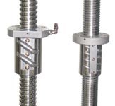
Ballscrews are made in different diameters and pitch. These features determine the rotational speed, torque and horsepower the axis motor must have to move the table at a given feed rate and thrust. A ballscrew with a coarse pitch turns fewer times to move the same distance as a ballscrew with a finer pitch, but it delivers less thrust or requires a larger motor to achieve the same result.
Heat develops within the ballscrew nut depending on preload within the nut, ball size, number of circuits, ball nut design and screw diameter. The type and quantity of lubrication utilized may affect heat buildup. An independent test indicates that when ballscrew temperatures rise 1° C (1.8° F) in a 20-inch long ballscrew, it will grow 0.00023 inch, based on the expansion coefficient of steel, which is 0.00001134 inch per degree Celsius per inch.
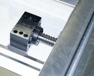
Typically, ballscrews are mounted fixed-not supported or fixed and supported. Fixed-not supported ballscrews are mounted at one end with angular contact bearings to reduce backlash and increase accuracy within the axis. Longer ballscrews require support at both ends to eliminate vibration, increase screw life and allow increased screw speeds. Preload within the bearing sets of either type mounting system also generates heat within the screw.
Another method, called stretched ballscrews, supports the ballscrew at both ends with opposing bearings mounted back to back to create the preload. As the ballscrew heats up and expands, the preload on the ballscrew relaxes. This condition can increase positioning error and reduce stiffness within the system. However for very long ballscrews, support and preload at both ends will help prevent the screw from bending.
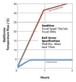
Cooling the ballscrews seeks to eliminate heat at the source. Some manufacturers cool only the nut, but this approach does not remove heat from the entire system. The screw retains some heat from the support bearings as well as some heat from the bearings in the ball nut. An alternative approach dissipates heat and maintains constant ballscrew length with a gun-drilled ballscrew through which flows a high-efficiency heat transfer agent. Where Fadal has adopted this approach, the company uses refrigerated ethylin glycol as the cooling agent.
Linear Scales And Thermal Growth
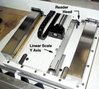
The linear scale utilizes a precision glass scale, which is sealed from contaminants. Typically, linear scales are mounted directly to the casting and as close to the ballscrew as possible to minimize abbe’ effect (error resulting from pitch and yaw that affects flatness and surface finish). Isolated from direct contact with the ballscrews, a main source of heat, scales experience minimal effects of thermal growth. Some manufacturers utilize a heat shield between the ballscrew and linear scales to further reduce heat transfer.
Laser Doppler scales and laser scales are another type of encoder used to mitigate the effects of heat. Based on laser light and the principles of light wave diffraction to obtain very fine measuring steps, these systems offer a combination of high accuracy, extremely fine resolution and excellent repeatability. However, laser measurement systems are fairly expensive.
Thermal Growth In Spindles
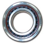
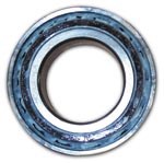
For high speed machining (12,000-15,000 rpm), spindle bearings with high heat dissipation qualities and low coefficient of friction are required. Many machine tool builders have opted for hybrid bearings, which combine ceramic (silicon nitride) bearings and steel races. Hybrid bearings feature less mass and higher stiffness, qualities that enable them to maintain shape. Hybrid bearings exhibit less inertia. Methods of spindle lubrication include the traditional grease-pack, oil-mist and air/oil systems.
Typically, air and magnetic bearings are used in high-speed applications with small tools and minimal load or in low-speed, heavy load conditions, such as grinding. While air bearings and magnetic bearings are free of thermal stability problems, at present they are unable to deliver the stiffness required for high-speed applications with heavy loads.
Compared to standard steel bearings, ceramic bearings feature higher stiffness because of higher Modulus of Elasticity (314000 vs. 208000 Mpa) according to Fred Krieger, engineer, NSK Corporation. Also, ceramic bearings operate at lower temperatures due to a lower coefficient of thermal expansion. Ceramic balls have less density (50 percent of steel). Lower coefficient of thermal expansion, as well as lower density of ceramic material, results in a more constant preload level or less of a preload increase while operating at high speeds. This is due to a smaller (thermal) expansion of the ball and less effect from centrifugal force (because of lower density).
Using ceramic ball material, it is possible to achieve a 20 to 50 percent speed increase over conventional steel ball bearings. When these ceramic bearings are properly selected and the machine is properly maintained, these bearings can be very long lived.
Lubrication Systems
Lubrication of all moving or rotating systems is essential, but the right amount of lubricant is critical for each type of system. For example, a way system with too much oil will float the riding member and make it difficult or impossible to machine workpieces to the specified flatness or parallelism. On the other hand, high-speed ballscrew systems with too much lubrication will experience a greater temperature rise because the balls will be distorted as they are forced to displace excess oil. Although damage is rare from this condition, accuracy is likely to suffer.
High-speed spindles are different altogether because all conditions, though similar, are greatly exaggerated. At 12,000 to 20,000 rpm or more, whether grease or some type of air/oil system is used, the quantity and placement of the lubricant are extremely critical. At these speeds, too much grease or oil will create ball and race distortions great enough to cause damage to both. In the case of ceramic bearings, damage to the race is the primary result.
The most popular type of lubrication systems includes grease pack, oil mist and air/oil. Grease is an excellent lubricant. Some specially designed greases have millions of “micro-fibers” that act like wicks to draw oil from the grease to the metal surfaces of the bearings. However, grease has its drawbacks. In very high speed machining with long duty cycles and highly contaminated environments from machine coolants, these drawbacks become apparent.
For example, there is no such thing as a perfectly sealed spindle. As the spindle cools down, some moisture inevitably will enter the spindle cavity. Moisture, even in minute amounts, is detrimental to spindle life, which is one weakness of grease-pack spindles. An air/oil system, such as the one utilized on Fadal’s 15,000-rpm spindle, eliminates this problem with a constant flushing of the bearings. New oil is constantly entering the spindle, forcing out moisture.
Also, most grease-pack spindles reach a higher operating temperature than an air/oil spindle will. In some situations, grease-pack spindles can reach temperatures over 150° F, the point at which many greases will begin to break down and diminish spindle life. Most grease-pack spindles need a cool-down period that allows spindle bearings to be replenished with oil wicked out of the grease as the spindles cool. This cool down period reduces the duty cycle times and production output. In contrast, an air/oil spindle has a continuous duty cycle as it is constantly lubricated and cooled down by a continuous flow of cool air and new oil.
Some high-speed spindles, such as those used by Fadal, use an air/oil lubricating system with ceramic bearings and steel races to reduce thermal growth at higher speeds. A precise amount of steam turbine oil in droplet form is injected into the air stream, using as little as 0.025 cc of oil in 25 minutes. Excess oil is sucked out of the spindle housing to prevent over lubrication.
Vibration
Vibration reduces accuracy and repeatability, causes poor surface finish and premature tool wear, and contributes to early failure of system components. Vibration may come from the spindle motor shaft, pulleys, belt, gears, tool, toolholder, bearings with inadequate preload and the spindle. All of these components are balanced to a specified tolerance. If that tolerance is not adequate for the machining parameters applied to them, excessive vibration results. Other sources of vibration include axis motors, ballscrew alignment, harmonic resonance, drawbar, axis crabbing and the control’s processing speed.
To avoid vibration, the spindle and all its system components must be machined and ground to the tolerances that minimize vibration at higher speeds. The tighter the tolerance, the better balance and the lower the vibration. System balancing, when all components are assembled, is a must.
Any misalignment of the ballscrews causes vibration and contributes to the failure of ball nuts, motor couplers, and possibly the motor and amplifier. Misaligned ballscrews are usually detected from the loud noises they generate. The longer they run in this condition, the greater damage and the higher the cost to repair.
Machine tools have resonant frequencies like all mechanical systems, and they are subject to resonant vibrations because cutting forces produce harmonics beyond the fundamental rotational speeds or frequencies, for example, once per revolution and once per tooth impact. According to Tom Delio, vice president of Manufacturing Laboratories, Inc., a firm that specializes in high performance machining and machine tools, one or more of these harmonic frequencies can, at certain spindle speeds, coincide with the natural resonant frequencies of the machine and produce detrimental resonant vibrations. Depending on how active the particular resonant frequencies may be at the location of the cutter-workpiece interface, quality of the workpiece surface, level of stress at the tool tip, bearing loading, and to a small extent power consumption may be affected.
Modal frequencies can be addressed by redesign of the area that is causing the frequencies or by adding a damper. However, adding a damper requires identification of the mode shape of the frequency, determining where the frequency is most active and then locating an area where a damper can be fitted that will absorb the energy of the mode.
In some instances resonant frequencies may be sufficiently high that resonant vibration does not occur due to the inability of the machine to reach a high enough spindle speed. This situation is most likely with conventional speed machines. Additionally, all machine tools can encounter resonant vibrations due to harmonic excitation of resonant frequencies of flexible workpieces. The most effective correction with these types of problems is to add damping to the offending structure.
Another source of vibration, axis crabbing, is caused by one way or guide moving ahead of the other in alternating fashion. Crabbing may be caused by incorrect adjustment of gibs or misaligned linear rails and trucks and can be corrected by properly adjusting these components, unless it is caused by the design of the machine itself (for example, where the ratio of width to length of mating systems is excessive). Correcting poor design to eliminate crabbing is very expensive.
Vibration may cause fretting, which occurs when mating surfaces of toolholder and spindle taper are subject to vibration and rotating motions during milling. These motions cause minute particles of material to pull out of the mated surfaces, leaving a rust-color powder.
Vibration in a machine tool cannot be eliminated entirely. Vibration, however, can be reduced by the design of machine castings and the use of Turcite and Moglice, which are known for their damping characteristics. The weight and size of castings and the location of webs, ribs and bosses also effect vibration-damping characteristics.
According to Scott M. Robie, business unit manager of ITW Philadelphia Resins, a formulator of polymer castings for the machine tool industry and other industries, some castings are filled with composite materials to damp vibration. However, damping material must be located in specific areas in the vibration path to absorb the frequencies, or there may be little or no improvement. Mr. Robie adds that polymer castings offer excellent rigidity and damping characteristics, but their mass ratio is about 3:1 of cast iron, which means casting wall thickness may be up to three times as thick as equivalent cast iron structures. Polymer castings heat up and cool down more slowly than metallic structures, a quality that can be used as an advantage when designing new equipment. They do have similar coefficients of thermal expansion to cast iron and steels, but due to their lower thermal conductivity they tend to maintain their shape longer and can be used to minimize thermal distortion in critical areas such as scale mounting surfaces.
Vibration can also be caused by an overloaded control, that is, it has too many axis moves or tasks to perform, and speeds are set so high that the machine is subjected to sudden starts and stops, the jerky motion that affects surface finish and increases wear on machine tool components. This can be resolved by tuning the servo axis motors. Some machine tools have a feature that enables the operator to change speed and accuracy parameters, such as chordal deviation, servo stiffness, acceleration, deceleration and feed rate, for a specific tool or application based on observation.
Linear guides and box ways impact vibration damping as well. The correct choice depends on the application. Box way systems offer longer life, while linear guides have more moving parts that can wear out. Traditional linear guides offer less damping than box ways. However, hybrid linear guides offer increased damping capabilities, and additional damping in the machine structure can mitigate some of the vibration. Linear guides can provide a good solution for high speed, low-force applications, while box ways provide a good solution for high-force applications.
Only Productivity Counts
As high speed machining moves into the mainstream, more shops are finding that a higher speed spindle by itself is not necessarily a high productivity solution. All the systems, from the castings and spindle through the control, have to be designed to take advantage of the high speed machining capabilities. So, finding the ideal machine for high speed machining is a matter of matching application needs to the best combination of high speed and high force or low force features and options.
About the author: Dean Gibson is an engineer at Fadal Machining Centers.
Related Content
How to Accelerate Robotic Deburring & Automated Material Removal
Pairing automation with air-driven motors that push cutting tool speeds up to 65,000 RPM with no duty cycle can dramatically improve throughput and improve finishing.
Read MoreRead Next
One Way To Select A Vertical Machining Center
The 'perfect' machine is one that best matches your needs. Knowing what you need is the key.
Read MoreHigh Speed Machining In The Mix
Can shops have machining centers versatile enough to handle both high speed and conventional cutting? Yes, but with some qualifications. And contrary to what you may be hearing, mechanical qualities may be the most important factors of all.
Read MoreSetting Up the Building Blocks for a Digital Factory
Woodward Inc. spent over a year developing an API to connect machines to its digital factory. Caron Engineering’s MiConnect has cut most of this process while also granting the shop greater access to machine information.
Read More





.png;maxWidth=300;quality=90)


