High Speed Machining In The Mix
Can shops have machining centers versatile enough to handle both high speed and conventional cutting? Yes, but with some qualifications. And contrary to what you may be hearing, mechanical qualities may be the most important factors of all.
Share


Some shops want to do high speed machining (HSM), but don't want to do it all the time. Maybe they can afford to do the necessary HSM process planning for longer production jobs, but not for the short runs. Maybe they deal with a variety of materials, some of which lend themselves to HSM, and some of which don't. Perhaps they cut tool steel conventionally during the day and graphite electrodes at high speeds at night.
And maybe they can't quite justify earmarking an expensive piece of equipment only for narrowly defined process capabilities. They need to execute both high speed and conventional cutting on the same machine.
That leaves a shop with an equipment dilemma. Should they take a basically standard machine and do their best to soup it up with higher speed spindle and control options? Or would it be better to bite the bullet and purchase a machine truly optimized for the HSM process, recognizing that the gain in high speed performance will probably come at a price of reduced low speed cutting capabilities and durability?
That's a tough call for even the most experienced machine tool buyers. While we'd all like a "universal" machine well suited for virtually any cutting condition, the simple truth of the matter is that you can't have it all, or at least for a price that most shops are willing to pay. With each machine design consideration comes a series of tradeoffs. And the trick of proper machine selection is to find a design that offers the best total performance across the entire span of processes that you're expecting to run.
The following are some of the most important mechanical machine design elements to consider if you are looking to get into high speed machining. Why focus on just mechanics? For one thing, the control aspects of HSM have been thoroughly discussed in this magazine and other venues over the last few years. Indeed, the coverage has been so extensive that one might get the impression that all you need is a fast CNC to make a machine perform accurately at high feed rates. But high CNC performance will not translate into high cutting performance and reliable operation if the mechanical system is not up to the task. So we'd like to take this opportunity to add a little more balance to the discussion.
For another thing, CNC performance is quickly becoming a leveling factor among machine tool builders. Many machine tool builders are using essentially similar CNC technology, and in some cases, the very same CNC models. If so, what now distinguishes one machine from another is how the whole machining system is conceived, built, and integrated with its servo control system.
Don't let anybody kid you about high speed machining. Mechanics matter, in many ways more so than with conventional machines. You'll see it in the very first cuts, and you'll come to appreciate it even more as you see how the machine performs over time.
Physics In Motion
This is not to say that control issues are unimportant. Quite to the contrary, a high speed machining system must have a CNC with the raw power to process "data-dense" part programs quick enough to keep up with high feed rates, and with the sophistication to manage axis acceleration/deceleration functions in such a way that high actual feed rates are maintained without compromise to accuracy.
But even if two different machines offer the same CNC functionality, there probably is still going to be significant differences in cutting performance. For the time being, let's set aside the issues of spindle horsepower, rigidity and those other traditionally regarded mechanical machine tool characteristics. Let's just talk about a machine's ability to quickly and accurately get to a commanded go-to point. Processing the data fast is only half the job. The machine must also quickly move a substantial load in a 3D space, and that's a demanding task indeed.
Put this picture in your mind: If you are contouring, two or three servomotors have to be activated, each turning a long metal ballscrew that is mechanically converting that rotary action to linear motion. The motors must overpower, not only the relatively predictable mechanical resistance of the machine components, but also the broadly variable factors of workpiece mass and cutting forces. How quickly and accurately a machine tool can move all that metal is the acid test of how well it performs in high speed machining.
Moreover, you can't discern much about a machine's true motion capabilities just by looking at the specs. Why? Consider, for example, the machine's published top feed rate. If two different machines each can do 1,000 ipm, they might seem to be roughly equivalent. But just because two servomotors can achieve the same speed doesn't mean that they can accelerate at the same rate. All other things being equal, the machine with the best acc/dec characteristics (which is a function of servomotor power and responsiveness) will execute a part program faster and much more accurately.
Even the published acc/dec curves won't tell you everything you need to know. It's one thing to cycle an empty machine, quite another to move a table carrying 10,000 pounds of tool steel. The same goes for published accuracy and repeatability specs. Hitting a spot in a controlled accuracy measurement is a very different kind of test than dynamically machining a part under heavy loads at 300 ipm.
You also have to consider the tradeoff between cutting speed and power. While spindle drive technology has grown much more capable across the full range of operation, to get high-end speed you'll still have to sacrifice some torque capacity at the low end of the range. And you need to understand at what rpm will the machine deliver full horsepower.
A Word Or Three About Spindles
Achieving high performance in a variety of applications thus requires a machine design that doesn't just do one or two things well on paper. It requires a harmony of design of all the machine's components into a well-proportioned machining system. While heavily stressing an individual component of the system—such as spindle speed—may be appropriate for some narrowly defined applications, it will probably force tradeoffs in other areas that you may not be prepared to make if you hope to get a broader range of service from your investment. Looking a little closer at some of the individual components of the machining system will help explain what that means.
Spindles are a good place to begin. There is some remarkable technology available today that allows machining spindles as large as 40 taper to easily reach 20,000 rpm, 30,000 rpm, and higher. And if all you are doing is taking relatively light cuts in easy-to-machine materials, or very light cuts in hard or tough materials, then ultra high speed spindles may well be the best way to go. But don't expect years of life out these spindles, and don't expect them to fare well in a crash.
If you are cutting a variety of materials, and some of your cutting is going to be in a more conventional range of feeds and speeds, you probably want a more robust spindle. That means you are going to sacrifice some top-end speed, but you'll gain significantly longer spindle life. If you want a large measure of the benefits of HSM, plus a level of durability closer to that of more conventional machines, staying with a spindle in the 10,000 to 15,000 rpm range may be the better choice.
In any case, the higher the speed, the more critical spindle runout and balance become. That has everything to do with with the quality and precision of the spindle machining and assembly process, but also the quality of the purchased components—specifically, the bearings. You'd be surprised to find how much bearing quality can vary from machine to machine. In the simplest terms, higher quality bearings are closer to geometric perfection—they literally are rounder. That serves to hold runout to a lower value, which in turn significantly enhances overall spindle service life. In fact, if you have an older machine in your shop that is still cutting surprisingly well, you can bet it has a superior grade of bearings in the spindle. It's all the more important in higher speed machining where the ill effects of runout are magnified, resulting in premature wear of spindle and cutting tools, as well as significantly diminished surface finish.
Another important aspect of a spindle design is the preload on the bearings. That is, bearings are essentially squeezed somewhat before any dynamic load is applied, which provides for more stable and rigid (to handle side loads on the cutter) dynamic characteristics. The question is: How much preload is best for the majority of your applications? While adjustable preload technology is available, it's mostly found only on very expensive machines. With more mainstream technology, you'll have to live with the preload you get from the factory.
If you intend to do some heavy, slower cutting, you must have a relatively high preload on the spindle's radial bearings. Otherwise, the spindle simply will not be rigid enough to deliver acceptable performance. On the other hand, if you intend to cut at sustained high spindle speeds, you need a light preload on the spindle bearings in order to provide minimal resistance and to keep friction to the minimum.
Spindle lubrication is extremely important as well. If you are running spindles below 5,000 rpm, grease lubrication works perfectly well. But as you approach 10,000 rpm, it quickly grows inadequate. Why? The thickness of grease is desirable at low speeds in a large part because of its propensity to adhere to wear surfaces. At higher speeds, however, the grease offers greater resistance than is desirable, which results in the generation of excess heat. Newer lubrication technology uses a mist of oil and air that is continuously injected into the spindle bearings as they run. The oil offers much less resistance than grease because it is a lighter, more fluid material and because there is much less of it. The bearings run significantly cooler because the light oil lube itself generates less heat, and because the injected air also helps dissipate heat.
Moreover, oil-air lubrication helps keep the spindle's internal components cleaner because the positive air pressure serves as a barrier to the penetration of cutting fluids and other contaminants. That's a particularly important point for shops that intend to cut abrasive materials such as graphite, one of the most common high speed applications today.
The newest technology is moving to mists of increasingly lighter oil-to-air ratios, which further enhances the inherent operating advantages of oil-air lubrication. These systems consume and release less oil overall, resulting in a cleaner shop environment as well as less tramp oil to deal with in the sump.
Accuracy And Heat
Another major issue with high speed machining is how to maintain mechanical accuracy within an extremely thermally challenging environment. All these mechanical components—bearings, ball-screws, and slides—are rubbing together, generating heat. The motors are generating heat. The cutting process is generating heat. And all that heat can physically change the shape of the machine's metal components that expand as they grow warmer and contract as they cool.
High speed machining ups the ante across the board. The faster the motion, the more the heat. Besides the accuracy issues, the heat can accelerate machine wear as preloaded bearings and other mechanical components "grow" into higher contact loads, and as higher thermal conditions accelerate the wear of almost any metal part.
Cooling the ballscrew helps, and a number of builders use systems that run coolant around servomotors and/or through the ballscrew itself. Still, there will be thermal variation, particularly as the whole machining system progresses from a cold start to a more thermally stable running state—a phenomenon many shops see over the first hour of operation every morning.
A design characteristic Mori Seiki thinks is important to counter this effect is to capture the ballscrew at both ends, initially setting it up in a preloaded condition. That is, the ballscrew is literally stretched (if only by a very small amount) between two fixed thrust bearings. As the screw warms through operation—and the metal "seeks to grow"—the tension on the system is relaxed, yet the screw remains relatively constant from a dimensional standpoint. No mechanical system is perfect, of course, but this arrangement is more dimensionally stable than cases where axially unloaded ballscrews are fixed at only one end, and thermal growth is cast out in a single direction.
While this all may sound like splitting hairs, this mechanical accuracy is particularly important in high speed machining. For one thing, just about any shop that watches their machines closely in the morning knows that the warm-up phenomenon is real. More subtle but no less significant is the mechanical precision required for high speed contouring. To maintain both accuracy and a high quality surface finish, common practice today is to generate part programs with extremely small point-to-point moves. (Even in cases where programs are using curve or circular interpolation commands, the fine interpolator inside the control is driving the servos to a succession of discrete positions.) That requires the mechanical system to accurately execute moves so small that you couldn't even calculate them quickly enough a few years ago. The mechanical system's ability to execute these moves has a tremendous impact on surface finish.
And it's not just the management of a ballscrew's thermal condition that matters. It's also the precision to which the screw was manufactured in the first place. Have you ever really thought about why machines with linear scales are so much more accurate than those without scales? A common perception is that scales are just inherently more accurate than a rotary feedback device on the servomotor. But the larger truth of the matter is that scales are used to compensate for the mechanical innacuracies of the machining system. There is the obvious real-time benefit of this as each machine position reading is taken after the mechanical inaccuracies have naturally taken their course. Also, CNCs have remarkable capabilities these days to map a machine tool's mechanical error profile, and then to compensate by offsetting the machine's coordinate system at various points along each axis. Machine builders use this capability to enhance a machine tool's accuracy profile initially, and savvy users use it to maintain a higher degree of accuracy as various machine components settle or wear.
There is nothing inherently wrong with employing these accuracy-enhancing techniques, and virtually all machine tool builders use them to one degree or another. But the fact is that you can get linear scale-like accuracies without scales if the machine is mechanically accurate in the first place. It's better to build the machine that way, and then save the comp for wear.
Fit For Life
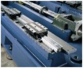
There are some components of machine design that people tend to take for granted, but shouldn't. For example, it is generally understood today that a high speed machine is probably going to have linear guide rails rather than box ways. Putting each of the machine's major moving components on bearings this way reduces friction, requiring less force to execute axis moves and generating less heat. What many people fail to recognize, however, is that there are pretty substantial differences in the guides themselves.
It's not just the size of the rail that matters. It's also the radial and axial load capacities versus the coefficient of friction. If you are just cutting aluminum, ball bearings are what you want. But if you want to take some heavy cuts in steel, roller bearing guides may be the better choice. Preload is an issue too. Linear guides don't just have bearings on the top of the rail, but on the sides as well. Just like spindles, a higher preload will increase rigidity, but that will come at the cost of higher rolling resistance and inertia. The surface on which the guide is mounted is also important. Is it shimmed? Is it scraped? On a good quality machine, great care goes into making certain this surface is as flat and the guide is mounted as straight as possible.
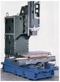
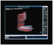
Design of the machine's moving structural members is absolutely critical. The days of buying machines by weight are gone. You still need dynamic stiffness; in fact, you need more of it than before. But that rigidity now must be achieved with much lighter components. With the help of finite element modeling tools, machine tool builders are making good progress in taking weight out of castings, but there is still a way to go.
It's hard for users to evaluate many of these components, of course, because they are buried deep in the machine, and the impact of any single design element can seldom be isolated from the rest of the system. It's how all these components function in concert that matters, and that often can be discerned only through comparative cutting tests.
One aspect of performance that users can see and even control is how the motion control system is tuned. Some machines seem to be great at cutting a straight line fast, but terrible at cutting a good quality circle. Or conversely, they cut a great circle but can't seem to do anything very fast. If so, that may simply be due to how the servodrives are tuned.
That is, the responsiveness of a servo system is adjustable within a range, with the basic tradeoff being speed versus accuracy. In the old days, servos were tuned by adjusting a range of potentiometers on the drives—a fussy process that was best handled only by highly skilled professionals. Today, however, these parameters are established in the control system software, which makes them much easier to set, and reset, depending on the required system performance. Machine tool builders typically tune the system at the factory somewhere near the middle of the range. But those settings can often be altered, even by machine operators. On most Fanuc controls it can be done with a simple G-10 command right in the part program. In Mori Seiki's case, a feature allows system tuning to be set automatically. In real time, the CNC analyzes the severity of the upcoming contours and axis velocity, and then adjusts system tuning based on the required level of accuracy. It in essence is setting a tolerance on the accuracy not unlike the tolerance that is set in CAM systems to generate the points of a contouring program.
It's surprising how much difference altering these settings can make. In the case of one of Mori Seiki's customers, some test parts were cut to establish the best possible cycle time on a certain machine. Once satisfied with the process, they went into production on identical machine models only to find that the cycle time had doubled. A quick analysis found that the production machines were simply tuned to a higher-than-necessary tolerance, and the cycle time was quickly brought back in line. In another case, a customer was cutting very detailed molds where accuracy was far more important than cycle time. Once he realized that he could control the system tuning, he set it way to the high end. While his cycle time went from the previous 4 hours up to 11, he was able to machine a level of detail he never imagined was possible.
The final issue to consider with high speed machining centers is how well the machine will perform over time. Besides the rough treatment that is an unavoidable condition of the shop floor, users need to recognize that they simply are going to put more "miles" on a high speed machine than its conventional counterpart because it is quite literally traveling more distance per part. Why? Generally speaking, in high speed machining you trade speed for load. Fewer, heavier cuts are replaced by more numerous, lighter cuts. In die/mold finishing routines, for instance, it's not uncommon for shops to reduce stepover distances to a third of what they ran conventionally. This results in a much smoother and more accurate machined surface, of course, but it takes three times the travel to get there.
And that brings up reliability issues. Given the high rpms, wear on spindle bearings is fairly obvious. But there are also issues with all the mechanical components of the linear motion systems as well. From the builder's standpoint, you even have to take account of such seemingly minor issues as the fact that the balls in the leadscrew units are recirculating at much higher velocity, which accelerates wear throughout. That lead Mori Seiki to change the material in the ball return tubes to enhance the wear resistance and to reduce the coefficient of friction, which also serves to enhance the thermal performance.
But that's stuff for builders to worry about. All users should have to focus on is how to get the most good parts out by the end of the day, or month, or year. You can bet your bottom dollar that a mechanically sound machine will provide the best return over time.
About the author: Marlow Knabach is the applications manager at Mori Seiki U.S.A., Inc. (Irving, Texas).
Read Next
5 Rules of Thumb for Buying CNC Machine Tools
Use these tips to carefully plan your machine tool purchases and to avoid regretting your decision later.
Read MoreBuilding Out a Foundation for Student Machinists
Autodesk and Haas have teamed up to produce an introductory course for students that covers the basics of CAD, CAM and CNC while providing them with a portfolio part.
Read MoreSetting Up the Building Blocks for a Digital Factory
Woodward Inc. spent over a year developing an API to connect machines to its digital factory. Caron Engineering’s MiConnect has cut most of this process while also granting the shop greater access to machine information.
Read More


.jpg;maxWidth=300;quality=90)


