Feature Recognition—The Missing Link To Automated CAM
Software that analyzes design geometry and identifies what is a pocket, a hole, a slot or another machinable shape promises to have a major impact on the productivity of CNC programmers.
Share


A famous poem based on a fable from India describes six blind men who encounter an elephant for the first time. Each one touches a different part of the animal's body. The one who feels the tusk declares that an elephant must be very like a spear. The one who grasps the tail insists that an elephant must be very like a rope. The one who catches the trunk says that an elephant must be very like a snake. Another proclaims that the elephant's floppy ear is very like a fan, and so on. Each of the blind men is partly right and each is partly wrong, the poem concludes.
In manufacturing, of course, there is no room for anything but being entirely right about how to machine a workpiece in order to fulfill the designer's intent. Part features as represented in design geometry must be identified correctly and linked with the appropriate machining strategy because nobody wants to end up making white elephants on the shop floor. In the world of CNC machining, this essential job of interpreting design data usually falls to the CNC programmer.
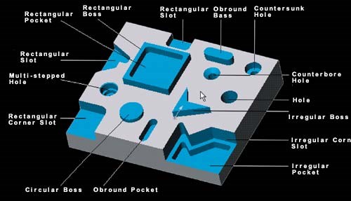
Today, many developers are working on ways to automate these interpretive steps. Feature recognition technology is an emerging tool for this purpose. Feature recognition means identifying the design geometry that represents holes, slots, pockets, bosses, fillets, chamfers and other design elements that can be machined. Automating or streamlining this process is a big help to the programmer.
With computerized feature recognition, programmers can be more productive, relieving pressure on shops that can't find enough qualified programmers. Part programs can be prepared in less time, easing the burden on overworked programming departments and eliminating a major bottleneck in work flow. Programmers can spend less time on repetitive tasks and more time on programming challenges that build skill and test creativity. If all this happens, then fewer mistakes and omissions would occur.
More important, feature recognition complements knowledge-based machining as a genuine step toward automated CAM. If machinable features can be identified automatically, these features can be linked to corresponding machining routines stored in a database. This linkage can be automated as well. The next step is tool path generation, which is already highly automated in most CAM packages. Put it all together and you have something very close to "push-button CAM."
Feature recognition is essential to automating other manufacturing applications. Cost estimates can be prepared with a few mouse clicks and much less guesswork. Requests for quotes can be fulfilled more expeditiously. Inspection routines for computer driven coordinate measuring machines can be generated in short order. Other analysis and planning applications will likewise benefit.
Feature recognition also plays a key role in efforts to create a digital product model that can be used directly as part program input, bypassing the CAM programming process altogether. This product model will someday include all of the clues that a future generation of CNC units will need to generate the data for axis motion. There will be no separate part program as such. The product model itself will function as a universal part program, serving as machine input for any machine capable of producing the part. Now the whole world becomes your factory, with the Internet acting as your global DNC system.
Push-button CAM and universal part programs?? Although these sound like futuristic predictions, they are already realities. To be sure, these concepts are not yet fully perfected, and some advanced aspects are only in the planning stages, but it's surprising how much is actually happening. And feature recognition is at the core of these breakthroughs.
Feature Recognition Takes Shape
Software developers have been working on computerized feature recognition for almost two decades. In the past, most of this effort has been in academic circles, the subject of numerous master's and Ph.D. theses in engineering graduate schools. What has promoted commercial applications of feature recognition in the last few years is the development of 3D solid modeling and its widespread adoption by CAD/CAM users.
With 3D solid modeling, the CAD file now has information about what's between or around surfaces. A box shape with a solid volume inside is a boss; a box shape with a solid volume only on the outside is a pocket. This new level of information is the enabler that makes solid modeling the precursor to feature recognition.
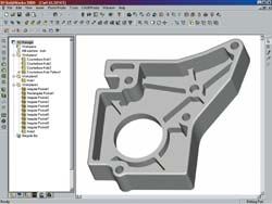
A number of leading CAM companies offer some sort of feature recognition capability in recent releases of their products. CAMWorks and ProCAM II from TekSoft Inc. (Phoenix, Arizona) are notable because feature recognition is a key part of their underlying technology, which is based on developments in solid modeling. ProCAM II is a stand-alone solids-based CAM package for PCs and workstations while CAMWorks is a product that is fully integrated within SolidWorks, the popular solid modeling design system.
Feature recognition figures prominently in how these products are being promoted. The clear relationship between feature recognition and knowledge-based machining is very evident in these products, which also makes them interesting studies. This relationship shows how automated CAM is evolving, not only in these products, but also in other CAM packages that are following a similar course with feature recognition and knowledge-based machining in a solids environment.
CAMWorks is being billed as "the closest thing to point and click machining available." How close is up to the CAM market to decide, but the concept of point and click machining highlights the potential of feature recognition. This is easiest to see in the CAMWorks milling application. (Turning is also available.) This application starts with a 3D solid model created in SolidWorks or imported via IGES or other exchange formats.
Here is a somewhat simplified description of the steps to creating a CNC program to produce a workpiece represented by the solid model. The user clicks on the Extract Machining Command. The software automatically analyzes the part model and identifies machinable features based on the part's geometry (the shape of the feature) and topology (how the features are related to each other). Currently, the software recognizes most prismatic features that lend themselves to 2½-axis machining. These generally fall into categories of holes with vertical walls, pockets and bosses. The set of prismatic features supported by a library of machining operations grows with each release of the software.
Areas not recognized automatically are established as machinable features through an Interactive Feature Recognition function. Essentially, the user responds to a series of queries in a dialog box until the system has enough information to define the area as a feature.
The concept of a machinable feature is critical because it is the logical link to knowledge-based machining. Pockets, holes, slots, bosses and so on are features because they can be defined by the machining steps commonly followed to produce them. For example, for a certain class of holes, it is accepted practice to drill a pilot hole, do a rough drilling operation, and then do a reaming operation. This is machining knowledge—how to drill this kind of hole.
So once CAMWorks has recognized the features, they are listed by workplane in a feature tree following the order in which they were recognized. Interactively recognized features are also inserted in the tree. These features then can be linked to machining routines and corresponding cutting tools stored in a database. The database includes machining parameters such as speeds and feeds that match the operation, the selected tool, and the workpiece material. The user can let default values be applied, or the database can be customized to reflect shop preferences. Connecting features to proven machining operations is the genius of knowledge-based machining.
The next command is to generate tool paths, based on the set of operations already established. Coordinate values for the required axis positions and motions are automatically derived from geometry inherent in the 3D part model, as most of today's CAM packages do. Another important feature in CAMWorks and ProCAM II systems is that the part and the CAM information are associative, that is, when the geometry of the part model is modified, changes to the machinable features result in corresponding changes in machining operations, machining parameters and tool paths. "Parametric" is another term used to describe this capability.
For many part models that can be machined in 2 ½ axes, all features are likely to be recognized automatically, and the default parameters are likely to be adequate, says Gary Fulton, president of TekSoft. In these cases, point and click machining is a fair characterization of this automated approach to programming. Automatic feature recognition contributes the most to the time saving delivered by the approach to automated CAM, Mr. Fulton says. He estimates that typical programs that once took two hours to prepare routinely take 10 minutes in CAMWorks.
Recognizing The Future Of Feature Recognition
Many of us have had the experience of visiting a site on the World Wide Web to find a favorite Web page, then clicking on the PRINT icon to get a laserjet copy of what we see on the screen of a laptop or PC. Regardless of whether the laptop is a Dell or a Gateway or the printer is a Canon or a Hewlett-Packard, the hard copy spits out in seconds. Why can't machined parts be produced as seamlessly? When will producing "hard copies" in aluminum or steel be as smooth as printing a document on a laser printer?
As it is, almost every step between the designer and the shop floor encounters vexing issues of data exchange, incompatible formatting, lack of interoperability, postprocessing and repostprocessing and so on. The grand international effort to alleviate these obstacles to the exchange of data is STEP. STEP is the STandard for the Exchange of Product model data. These standards specify a digital product data model so that virtually all essential information about a product, not only geometry, can be passed back and forth among computer systems.
One of the many projects under the STEP umbrella is the Model Driven Intelligent Control of Manufacturing program, which is being led by STEP Tools, Inc. (Troy, New York). This program is also known as the "Super Model" project. The Super Model concept being developed by this program will include not only product geometry, but also other information necessary for manufacturing the product. In keeping with the overall STEP strategy, all of the information will be captured as data files in a neutral format accessible by computer, regardless of the brand of hardware or software involved.
Data formats representing a library of specific operations that might be performed on a CNC machine tool are being specified by a proposed extension to the STEP family of standards. This extension is called STEP NC. STEP NC allows a complete database of machining information to be built around the digital product model and ultimately makes it possible for this enhanced product model to serve as machine tool input. This database is structured such that part features are linked to specific "working steps," generic descriptions of various machining operations. STEP NC working steps are roughly equivalent to machining commands formatted as traditional M and G codes.
Here is where automatic feature recognition comes in. To build a Super Model, product geometry has to be linked with STEP NC working steps, exactly the way machinable features must be linked to proven machining routines in the knowledge-based machining concepts previously discussed. Automatic feature recognition is one of the key enabling technologies that advances the Super Model toward its destiny.
In concept, a machine tool control unit with an Internet connection could access a database of super models, download a selection to memory, then execute it as a part program to machine a corresponding workpiece from the appropriate piece of stock or blank casting. As long as the control unit is STEP NC compliant and the machine tool capable of the operations, the super model is sufficient input to run the job. This is the "hard copy" manufacturers have always dreamed about.
That this dream can come true was demonstrated in November 2000. The occasion was the third meeting of the Industrial Review Board (IRB), which helps the Super Model project stay in touch with the vendor and user community. The Watervliet Arsenal in Watervliet, New York—America's oldest—provided the setting for this demonstration of some of its newest technology.
Keeping In STEP
The demonstration started with a solid model of a prismatic workpiece created in CADkey. The model included holes, slots and pockets of a rather simple sort. With the IRB and invited guests looking on, the product model was translated into the STEP format (almost all CAD systems have STEP translators today) and downloaded to a feature recognition system. This software analyzed the product model and recognized the areas to be defined as features for machining—in this case a slot and two counterbored holes. A pocket was also defined as a feature using interactive feature recognition tools.
Using STEP NC, technicians assembled a database of machining operations, cutting tools and machining parameters of feeds and speeds. This database was given XML codes and posted on a Web site. XML is an Internet language that tags data so other applications can find the types of data needed for display or processing.
To show that this Super Model could serve as machine input, it was downloaded from the Internet to a Bridgeport controller on a Bridgeport knee-type vertical milling machine. The control unit had been modified to use the Intelligent Interface developed by the Super Model project for reading this manufacturing data. From the Super Model database, this interface extracted the information needed to machine the slot and drill the holes. EZCAM shop floor programming software, installed on the control unit, generated the tool path as M and G codes. (A STEP NC interface yet to be developed will interpret STEP NC super models and generate machine code directly executable by the servo system, without the M and G codes required by controls under the old RS274 standard.) The test part was machined in wax to conclude this part of the demonstration.
The same demonstration was repeated, starting with a revised CAD file in which the slot was lengthened. This showed the flexibility and resilience of both the concept and its current realization.
Where Tolerance Is A Virtue
The CAM software with feature recognition that was involved with this demonstration is FBMach. FBMach is under development by Honeywell Federal Manufacturing and Technologies (FM&T), operator of a government-owned weapons production plant in Kansas City, Missouri. FBMach is part of a suite of software libraries for planning and organizing manufacturing operations based on solid modeling technology. According to Bill Simons, a member of the information technology staff at Honeywell FM&T, this software takes a rather different approach to part features and feature recognition, making it distinctive in several key aspects. These may be a clue to what lies ahead in the development of feature recognition.
FBMach was created to support manufacturing applications at the government plant in Kansas City, but it is available for licensing as a commercial product. The software runs on PCs or workstations with Microsoft's Windows NT, Windows 2000, or Windows 98 operating systems.
FBMach (short for Feature-Based Machining) was designed to help planners look at a solid model from a manufacturing perspective. Manufacturing processes such as CNC machining are concerned with pockets, holes, slots and so on. Like examples of other feature recognition, FBMach is a tool for analyzing a solid model and identifying logically related geometric entities as features for machining. The entities recognized can be defined as features either automatically or interactively.
However, machining is not just a matter of dealing with shapes. Machining is also a matter of tolerances—how well a shape meets various requirements. A shape produced on the shop floor must not be too big or too little; it must be in the right place for its purpose; it must not be too close to or too far from other shapes; it must be straight enough or round enough as called for; and the surface must not be too rough or too smooth. This is the Goldilocks reality of life in the factory.
Because planners have to concern themselves with the size, location, form, orientation and surface finish of shapes, FBMach was developed along with FBTol (short for Feature-Based Tolerancing). FBTol provides a set of tolerance features so that designers can incorporate this critical information with the solid model. (Another set of features—Feature-Based Measuring—for measurement applications such as inspection routines is in the works.)
Mr. Simons believes that this ability to support multiple feature sets is what distinguishes this software the most. Today, part designers can use FBTol to make sure their tolerance definitions are complete and unambiguous.
Another distinctive capability: In machining applications, the system creates both surface-based machining features and volumetric machining features. A surface-based machining feature is based on sets of faces on the solid model—the "skin" that represents the feature and shows what the feature looks like, so to speak. The volumetric machining feature is represented by "delta volumes," which are solid bodies showing the shape and amount of material to be removed. Tool paths are determined by delta volumes in applications for generating CNC routines.
After features have been defined, FBMach users interactively identify "feature cuts"—step-by-step lists of separate machining operations. This list can then be arranged to form the appropriate sequence, creating a complete process plan. Certain machining parameters also can be associated with feature cuts at this point.
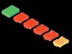
FBMach is able to generate "in-process models" that represent the shape of the workpiece before or after a metal removal operation. These models let planners see how a process plan or machining strategy progresses step by step until the final shape emerges. On the shop floor, in-process models show the machine operator what the part should look like before and after each cut, helping to visualize and validate machining operations. Mr. Simons points out that the planner can change the sequence of operations, and the software will automatically create new delta volumes and in-process models according to the new sequence. In-process models were used in the STEP-NC demonstration for process validation, and delta volumes were used as input to the shopfloor programming system on the milling machine.
At the moment, working versions of FBMach are limited to prismatic parts, although development of a turning application is on the project schedule. The feature recognition function is automatic for a wide range of features, but additional ones are being added continually. Building a product model database of feature cuts (the list of STEP NC working steps) is an interactive feature now, but plans call for it to be automated.
At the Kansas City plant, FBMach is currently used as a process design tool. In-process models are exported from FBMach to the plant's Unigraphics CAD/CAM system for part program creation. Mr. Simons believes that at the current pace of development, FBMach is bringing the plant much closer to implementing a "hard copy" approach to machining. "We're just a few years away from this goal. In the meantime, FBMach in-process models give our NC programmers a head start, significantly reducing the time and cost involved in getting part programs to the shop floor."
Changing Focus On Productivity
The emergence of programming tools such as automatic feature recognition may signal a shift in the route to increased productivity. What can be accomplished with higher spindle speeds and feeds, faster acting cutting tools, pallet shuttles and setup efficiencies has plateaued, although not all shops have reached the same high plain.
For many shops and plants, CNC programming is the elephant in the doorway, holding up workflow and tying up resources. But feature recognition and other strides toward more fully automated CAM are within sight and creating a new vision of streamlined manufacturing.
Related Content
Cutting Part Programming Times Through AI
CAM Assist cuts repetition from part programming — early users say it cuts tribal knowledge and could be a useful tool for training new programmers.
Read MoreThe Power of Practical Demonstrations and Projects
Practical work has served Bridgerland Technical College both in preparing its current students for manufacturing jobs and in appealing to new generations of potential machinists.
Read MoreHow this Job Shop Grew Capacity Without Expanding Footprint
This shop relies on digital solutions to grow their manufacturing business. With this approach, W.A. Pfeiffer has achieved seamless end-to-end connectivity, shorter lead times and increased throughput.
Read MoreCan ChatGPT Create Usable G-Code Programs?
Since its debut in late 2022, ChatGPT has been used in many situations, from writing stories to writing code, including G-code. But is it useful to shops? We asked a CAM expert for his thoughts.
Read MoreRead Next
Registration Now Open for the Precision Machining Technology Show (PMTS) 2025
The precision machining industry’s premier event returns to Cleveland, OH, April 1-3.
Read More5 Rules of Thumb for Buying CNC Machine Tools
Use these tips to carefully plan your machine tool purchases and to avoid regretting your decision later.
Read MoreSetting Up the Building Blocks for a Digital Factory
Woodward Inc. spent over a year developing an API to connect machines to its digital factory. Caron Engineering’s MiConnect has cut most of this process while also granting the shop greater access to machine information.
Read More


