Share


ECi Software Solutions, Inc.
Featured Content
View More
Autodesk, Inc.
Featured Content
View More
Oftentimes, grinding lobes and bearing journals is the final machining operation that completes an engine’s camshaft. This is still the case for a number of offerings from Comp Cams, a leading manufacturer of aftermarket camshafts and valvetrain components for race, show and street vehicles.
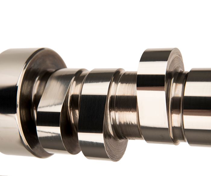
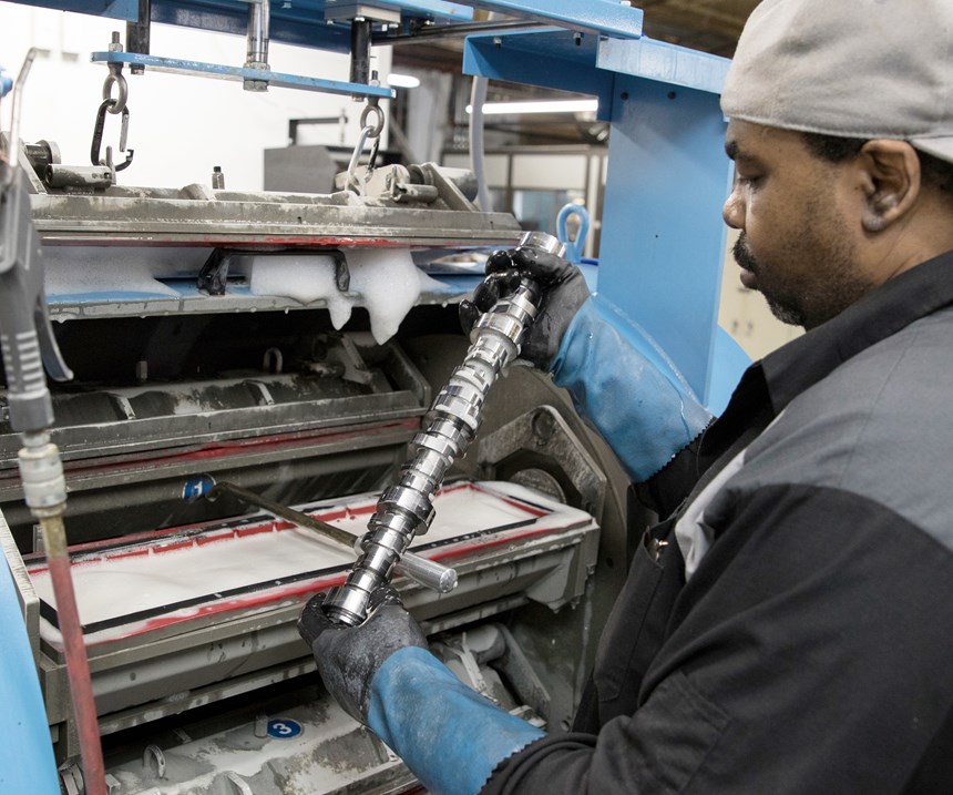
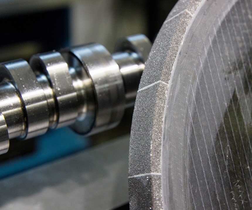
The Memphis, Tennessee-based company has continued to adopt new grinding technology over the years, and now has nine computer numerical control (CNC) grinding machines using carbon-fiber-hub, cubic-boron-nitride (CBN) wheels that are profiled and trued on the machines using rotary diamond wheel dressers. It also recently has introduced a new lobe and bearing-journal finishing process for one of its most popular roller-lifter camshaft lines that not only makes the camshafts look better, but more importantly, extends their lives by reducing abnormal, premature lobe wear. The kinetic finishing process does this by removing tiny peaks of material left behind after grinding while also minimizing the amount of side-to-side waviness across the surface of a camshaft lobe, thus increasing the effective surface-bearing area between a lobe and its mating lifter’s roller. This lowers the amount of localized stress the camshaft lobes experience during operation, minimizing the number of microscopic imperfections that could eventually propagate and become problematic on a macro scale.
Comp Cams calls its finishing process Micro Surface Enhancement (MSE), and it is currently available as a standard feature for the roller-lifter camshafts it offers for popular General Motors LS engines (introduced in 1995 for use in a variety of rear-wheel-drive vehicles) as well as custom racing applications for an added cost.
That said, MSE proved not to be a cure-all. In developing and refining the MSE process, the company realized it made sense to circle back to further refine its grinding process to generate a better overall camshaft lobe surface profile and finish to maximize the benefits that MSE offered.
Circling Back
Comp Cams is no stranger to the pages of Modern Machine Shop. In 2011, I visited with Billy Godbold, valvetrain engineering group manager, who explained how the company had developed a process to turn and mill custom, powder-metal camshaft cores for racing applications complete from barstock using a twin-spindle/twin-turret Okuma LT300-MY turning center. (Camshaft cores have their primary features machined, but still require subsequent heat treating and grinding operations.) After learning a bit about MSE recently, I decided a return trip was warranted.
For a number of years, Mr. Godbold and his team have been researching various finishing processes to improve camshaft-lobe and journal-surface quality. He says some camshaft manufacturers (Comp Cams included, largely for custom racing camshafts) perform belt sanding. However, it is challenging to get a belt to provide uniform pressure on a lobe. This can cause a lobe’s surface to become even more wavy and the lifter’s load to be applied only to a lobe’s high spots. Plus, belt sanding does not remove any remaining burrs on the lobes’ side edges. In addition, this is still largely a manual process requiring a skilled operator, so it is not easily scalable for higher-production applications.
It is also possible to acid-etch the surface of the lobes, which anneals and softens the iron in their surfaces, and then polish the surfaces with media to smooth them. However, the etching doesn’t affect the carbide in the iron lattice structure of the steel, so the process can leave behind peaks of carbide, which become stress risers, or points of localized stress.
A third option is micro peening. This kinetic-energy process blasts the lobe surface with micro media, but it can create tiny craters that have stress risers around their circumference. Also, it is challenging to clean out all the media from camshafts after the micro-peening process.
Ultimately, Comp Cams discovered a manufacturer of centrifugal-barrel-finishing machines and worked with the company for a couple years to tailor that type of kinetic-energy finishing process to its camshafts. (Mr. Godbold withheld the name of said equipment manufacturer.)
The machines (Comp Cams has two) operate on a Ferris-wheel-like principle. Each has four drums, or baskets, into which a single camshaft and the polishing media are manually loaded and enclosed. These drums rotate in the opposite direction of the barrel rotation. During operation (typical finishing time for a camshaft is 15 minutes), the combined rotation of the barrel and drums creates two tons of force on the media and camshafts in the drums, and this force is distributed equally on the camshaft surfaces to evenly polish them.
Although some applications of this finishing technology use organic material as the polishing media, Comp Cams determined that denser, ceramic-composite media and higher rotational speeds worked best for its steel camshafts, not only to remove any peaks and to minimize waviness across the camshaft lobe because of the uniform force that is applied, but also to provide a high luster. Plus, the process also deburrs the side edges of the lobes and journals. In addition, the company found that this process, with a very dense media, served to impart compressive stresses into the surfaces, which slightly strengthens them. MSE's rust-preventive qualities also made it no longer necessary to coat camshafts in as thick of an oil as it used to do prior to packaging.
That said, while MSE proved to be an effective finishing process, precise measurements using an Adcole 911 camshaft inspection device and Zeiss Surfcom Flex 50A skidless profilometer showed that even further improvements could be realized by making changes to the grinding process to generate a higher-quality surface prior to MSE finishing.
Grinding Through Improvements
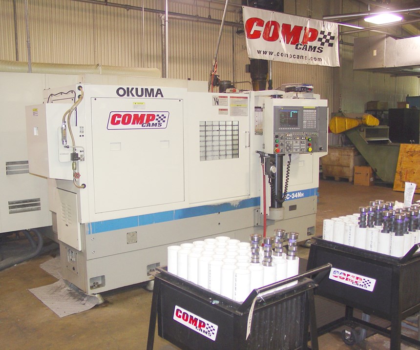
Today, Comp Cams’ eight Okuma GC-34 NH CNC camshaft grinding machines and single Landis 3L camshaft grinding machine use carbon-fiber-hub CBN wheels instead of steel-hub CBN wheels. Although these lightweight wheels are much costlier, they offer improved vibration damping, repeatability, predictable performance and less-frequent dressing (dressing is required after every 20 to 30 camshafts). The company found that using steel-hub CBN wheels on its rigid grinding machines sometimes caused camshafts to vibrate during grinding.
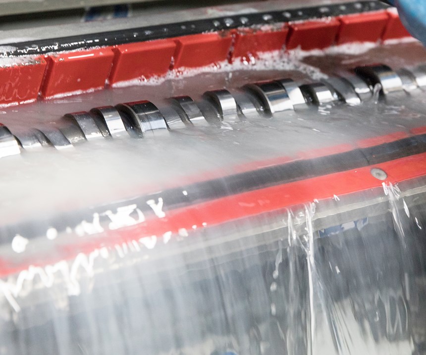
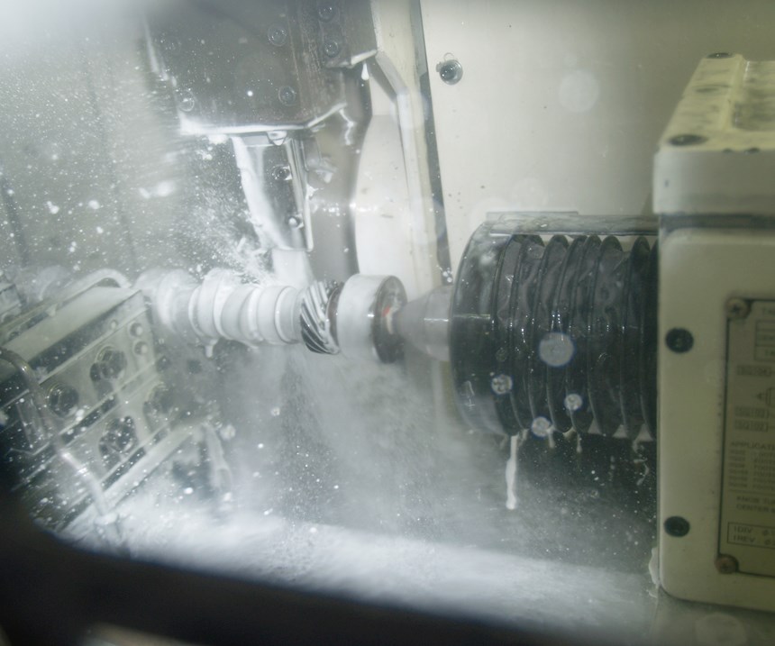
Comp Cams uses a variety of wheel brands depending on the camshaft being ground, and performs tests to measure the electrical current during a grinding operation when selecting grinding wheels for a given application. Higher current means more pressure and heat is created during grinding, which could cause burning, so it looks for wheels that grind with the least amount of current. It also added scrubbers to its grinding machines that shoot high-pressure streams of coolant across the face of the wheel during operation to remove any swarf buildup. Cleaning material out of the voids in the wheel surface reduces grinding pressure (and risk of burning the camshaft lobe and journal surfaces) as well as the frequency of dressing operations. Grinding tests proved that even less current was drawn when scrubbers were used because wheels could grind more freely when they were not loaded with swarf.
The company also settled on Castrol Syntilo 9974 heavy-duty synthetic metalworking fluid, which Mr. Godbold says is costlier than many other fluids, but it offers high, consistent lubricity with no need for a lubricity additive. In addition, the company went so far as to decouple coolant mist collectors from machines. Originally, the grinding machine mist collectors were mounted directly on the machine enclosures. However, it was determined that the mist collectors’ electric motors caused a slight amount of vibration that resulted in a small bit of measurable chatter in the ground camshafts. Now, the mist collectors are mounted on a frame separate from the machines.
Addressing the Dress
The final big change was refining and optimizing the wheel dressing process. William McIntyre, a manufacturing associate engineer for process development at Comp Cams, says the company received a good bit of input from Okuma and various grinding wheel manufacturers in developing its wheel dressing routines. As he explains, the first step in refining the dressing process was to get the speed ratio of the dressing and grinding wheels to the recommended 75 percent to minimize the risk of dressing chatter. In other words, the surface feet per minute (SFM) of the rotary diamond dresser was adjusted to be 75 percent of the normal SFM of the CBN wheels to provide the proper pressure on the wheels to enable proper surface fracturing. He says it is important not to reduce the grinding wheel speed during dressing because it can adversely affect grinding wheel concentricity, making it more difficult to balance at the normal rotational speed.
Comp Cams grinds so many types of material and surface profiles in lobes that it has multiple different dress parameters it uses depending on what’s best-suited for a given application. Mr. McIntyre notes that it can be challenging to determine the appropriate dressing wheel transverse rate across the grinding wheel. This rate is kept slow, but not so slow as to cause burning on the flanks or ramps of the camshaft. Too slow of a transverse rate will not open the wheel grains properly so the wheel will ultimately burn the cams during grinding.
In dialing in the dressing processes for each application, the company tested ground camshafts at set integrals to check for lobe surface topography, lobe profile and burning. Using a carbide disk that emulates a lifter, its two Adcole 911 camshaft inspection devices record the translating lifter motion for each lobe every 0.1 degree as it rotates the camshaft, meaning 3,600 data points are collected in a single rotation to a radial resolution of 1 micron. Comp Cams takes three measurements for each lobe (at the middle and on either side). This device records the motion of the lifter, determines if the lobe is convex or concave, and performs a fast Fourier transform (FFT) algorithm to check for grinding chatter.
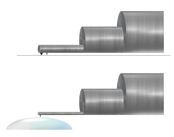
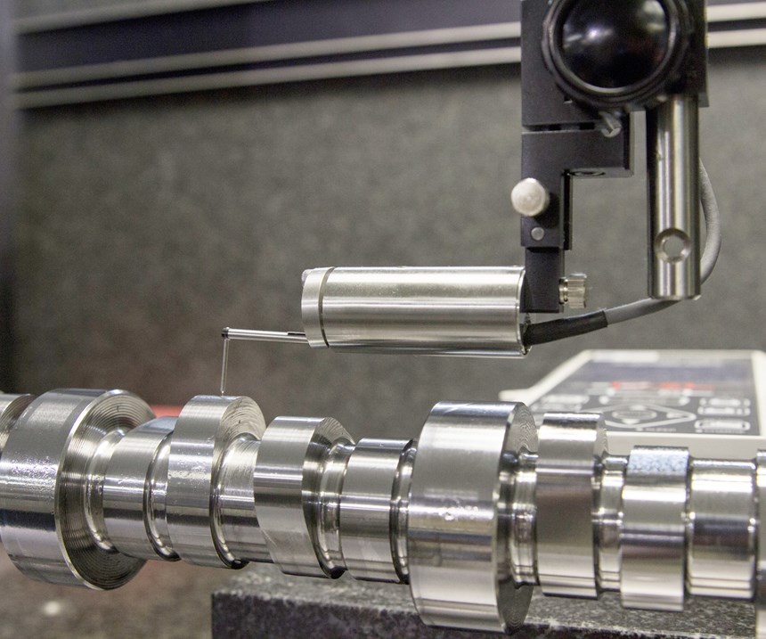
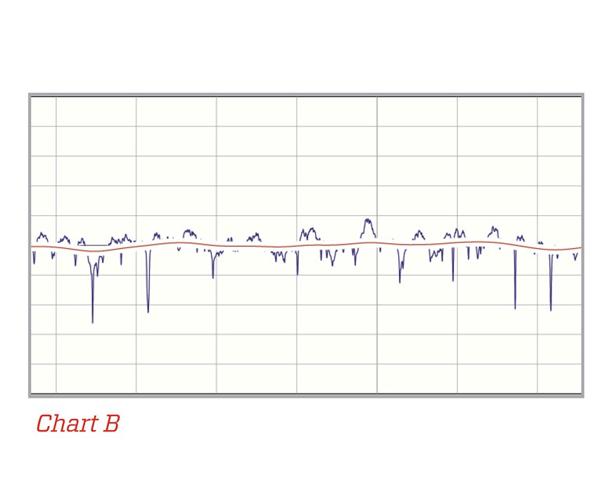
While the Adcole 911 is used to determine follower motion 360 degrees around lobes, the Zeiss Surfcom Flex 50A skidless profilometer measures lobe profile and surface finish longitudinally (side-to-side) across the lobe surface. It does this using a pointed diamond stylus that drops into any valleys and moves over any peaks in the surface to determine actual surface topography to a resolution of 0.000002 inch.
The profilometer is also used to check for appropriate lobe crown on roller camshafts. Mr. Godbold says that the surface of the lobes for roller camshafts should be slightly convex (with a bit of a crown in the middle), because the rollers on the mating lifters are also slightly convex. By having both mating surfaces slightly convex, the pushrod load (which can reach approximately 2,500 pounds for LS engines) tends to cause each surface to flatten a bit. Comp Cams shoots for a lobe crown of just a 0.0001 inch.
The company also uses Profile Master data analysis software from Digital Metrology Solutions to process and report the data gathered by the profilometer. Mr. Godbold says the software’s graphical interface is valuable in clearly communicating to manufacturing and quality control personnel how changes to the grinding process affect the end product.
To check for burned surfaces, Mr. McIntyre created a test station in which camshafts are first dipped in a bath of nital, an etching solution that is a combination of alcohol and 8 percent nitric acid, and then dipped in a bath of alcohol and 8 percent hydrogen chloride to deactivate the etching. This process will cause a significant color change of any burned surfaces because different material hardnesses react differently with these solutions.
Product Improvements
The various modifications of the grinding process ultimately enabled it to serve as “pre-polish” step on lobe surfaces prior to MSE processing. This enabled Comp Cams to use smaller media in the MSE process, because not as much material removal or surface pressure (as bigger media would provide) were required to remove material peaks and minimize profile waviness. Plus, bigger media tended to create new valleys in the lobe surface anyway, which would also reduce bearing area, meaning a second MSE operation with smaller media would have been required.
MSE was put into production in October 2017 for the company’s LS-engine camshafts and introduced at the SEMA show in Las Vegas, Nevada, later that month. Comp Cams plans to offer MSE for other camshaft lines down the road. Mr. Godbold says the bearing area for the company’s camshafts was approximately 10 percent 15 years ago and 15 percent 10 years ago. Now with refined grinding and MSE processes, the company is achieving 50 to 70 percent bearing area and reduction in peak roughness by 65 percent to more effectively spread the load on camshaft lobes to lower the stress they endure during operation for improved durability and reduced valvetrain noise.
The key in all this, however, was having the capability to precisely measure various lobe features as the company worked to improve its camshaft manufacturing process. As Mr. Godbold notes, if you are trying to improve a process but cannot measure to verify that improvements are being realized, you are ultimately just guessing.
Related Content
Sunnen Products Company Partners With Hendrick Motorsports
The partnership puts the new Sunnen SV-series honing machine in the Hendrick Motorsports engine operation alongside other Sunnen honing and engine building machines.
Read MoreThe Role of Surface Finishing in Modern Manufacturing: Trends and Best Practices
You’re attending IMTS to advance your business. Regardless of your role in the manufacturing process, considering how your parts will be finished is crucial. This article can help you understand trends in surface finishing and better communicate with your finishing partners.
Read MoreFaster Programming and Training Helps Automotive Shop Thrive
Features that save on training, programming and cycle times have enabled Speedway Motors to rapidly grow and mature its manufacturing arm.
Read More4 Tips for Staying Profitable in the Face of Change
After more than 40 years in business, this shop has learned how to adapt to stay profitable.
Read MoreRead Next
Registration Now Open for the Precision Machining Technology Show (PMTS) 2025
The precision machining industry’s premier event returns to Cleveland, OH, April 1-3.
Read More5 Rules of Thumb for Buying CNC Machine Tools
Use these tips to carefully plan your machine tool purchases and to avoid regretting your decision later.
Read MoreBuilding Out a Foundation for Student Machinists
Autodesk and Haas have teamed up to produce an introductory course for students that covers the basics of CAD, CAM and CNC while providing them with a portfolio part.
Read More





.png;maxWidth=150)


