Dial Down or Dial Up?
Vibration analysis may be the machining center’s missing piece. If you haven’t performed this analysis on your high speed machine, you probably don’t know what the machine can do.
Share


Hwacheon Machinery America, Inc.
Featured Content
View MoreExperienced machinists and NC programmers cultivate a particular response when it comes to the loud, ugly shriek of a poorly performing milling pass. Confronted with this evidence that the chosen parameters of the cut are not ideal, they reduce something. That is, they dial down some aspect of the process.
The specific parameter they reduce might be the depth of cut, the combination of speed and feed rate, or even the overhang length of the tooling. Whatever the parameter, “down” is the reflexive strategy for achieving better performance. Some of the more experienced machining personnel are skilled at reducing these parameters just to the extent necessary to achieve acceptable cutting. And in most shops, this reduction—this compromise—is likely to be the right response.
In high speed machining, however, this reduction is likely not to be the right response.
Indeed, the very essence of high speed machining is found in the way that it departs from this practice.
The parameters themselves remain important. Depth of cut, spindle speed and the length of the tooling all affect machining performance. Yet when the poor performance is indicated by chatter on a high speed machine, the “dialing down” can be counterproductive. Many shops with high speed machining centers actually waste capacity this way without realizing what they are doing.
In a high speed machining application, the way up to more stable cutting might still be “down,” but the way up might also be “up.” In the case of both spindle speed and tool length, there are times when the better answer to chatter is actually to raise one of these parameters. Strange though it might seem, there are cases in which a higher spindle speed and/or a less rigid tool can actually allow the machine to handle more aggressive depths of cut, simply because of the ways that these changes bring the vibration tendencies of the system into greater harmony. Shops that recognize this understand that part of the very nature of high speed machining is working within a spindle speed realm where it is no longer possible to determine, just from intuition or experience, what the ideal cutting conditions are likely to be. One machine shop that now knows this well is a part of Warner Robins Air Force Base in Georgia.
Military Milling
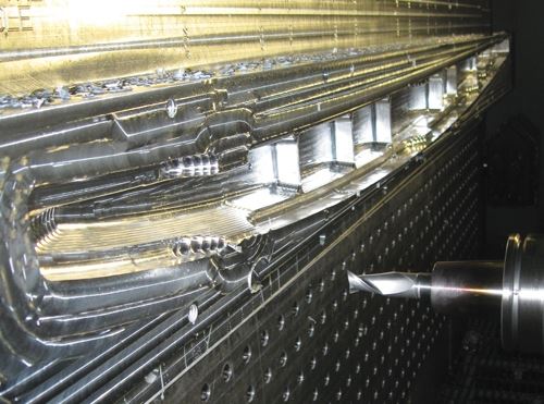
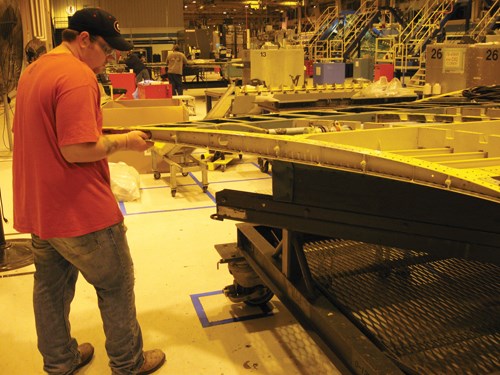
This fast-response shop is part of the 573rd Commodities Maintenance Squadron of the Air Force’s 402nd Maintenance Wing. The shop’s mission includes machining replacement parts for the fighter and cargo aircraft that fly to this base for service from all over the world. Because of the frequent need for these planes to return to action quickly, the shop often has to produce complex and critical parts in tiny quantities according to narrow lead-time demands.
Programmers David Devore and Mike Estes say that when this shop first began to use high speed machining centers, it unknowingly used them inefficiently. The shop broke tools frequently on these machines, including 3/4-inch end mills used for roughing. The shop’s response was to slow down certain cuts.
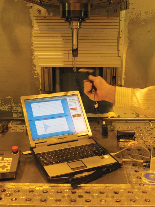
But when the shop installed its fastest machining center yet, a 30,000-rpm MAG 3 machine from Makino, it had the machine “tap tested.” That is, the shop measured the machine’s vibration characteristics by using a sensitive hammer to ring the tool in the spindle like a bell.
The aim of this analysis is to find stable cutting speeds for each tool/toolholder set that is used in a particular machine. At Robins, once these stable parameters were found and put to use on the new machine, the shop realized part quality, productivity and tool life that were all superior to what it had experienced with high speed milling up to that point. The difference was so great, the shop decided to perform the same analysis on its existing high speed machines as well. On these machines, the shop discovered that many tools were more stable, more productive and safer at speeds considerably faster than the speeds at which the shop had been running. After turning up the speed in line with these optimal parameters, the shop immediately began to run quieter, cut heavier and make better parts—all without routinely breaking tools.
Now, the shop is committed to running high speed machines using parameters that are based on vibration analysis. Beyond a certain speed, the shop has seen that this analysis is practically essential for realizing a machine’s full efficiency.
The reason for this relates to resonant frequencies. Every particular combination of machine, toolholder and cutting tool has specific stable speed values that permit the deepest cuts and heaviest metal removal. More explanation follows, but for now, it’s sufficient to say there is no way to infer from experience where these speed values might be. For Robins, there also was no practical way to find the stable parameters through test cutting, because the shop uses so many different tools. Therefore, the shop contracted with a source that could quickly measure all the machines’ vibrations and determine the best speeds and depths of cut for each of the tool/toolholder combinations that the machines routinely use.
Tool Dashboard
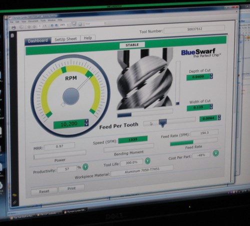
Now, say the programmers, cutting performance couldn’t be more different. The very environment of the shop has changed. With less chatter, machining is quieter. With the high speed machines capable of heavier depths of cut at higher speeds without tool breakage, the machines are more productive. And with the information that is now available about optimum machining parameters, the programmers themselves are more productive, too. One of the resources now available to them is a “Tool Dashboard” that lets the programmers precisely anticipate the performance and productivity of any set of cutting parameters chosen for a particular milling pass.
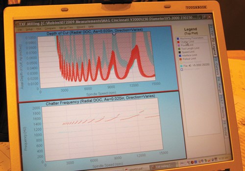
When a tool and toolholder are selected for one of the high speed machining centers now, optimum parameters are selected along with them. In fact, parameters based on the vibration analysis load into Catia automatically. When these cutting conditions need to be tailored (the depth of cut, for example, might not fit the cut that is required), then the parameters can be manipulated in the Tool Dashboard to find another efficient set of cutting conditions that continues to remain outside of where chatter sets in. Even the feed rate can be adjusted this way—testing it against the bending moment of the spindle. (See the illustration on the right.)
Warner Robins contracted with the company BlueSwarf both to perform the tap-test analysis and to provide resources including the Tool Dashboard. BlueSwarf is a firm specializing in machine-tool vibration analysis. The company sells a “Metalmax” analysis kit for shops to perform this analysis internally, but the company also performs the analysis itself on-site, for shops that want to contract out this work. The actual testing involves simply striking the tool while it’s in the machining center, hitting it with a sensitive hammer so that a sensor on the tool tip can capture the response. Because different combinations of tool and toolholder have to be tested separately, however, the complete analysis might span hours or days. Certain tool details such as corner radius don’t matter to the results, so not every actual tool number has to be tested. Still, the shop at Warner Robins needed to test 45 to 50 tool setups in every high speed machine.
Specific Speeds
Why, then, do machining centers behave this way? Why do high speed machining centers sometimes perform better at very specific speeds and/or particular tool lengths?
The answer has to do with the fact every mechanical system has some set of natural frequencies at which it inherently wants to vibrate, and a system of machining center, toolholder and tool is no exception. It has these natural frequencies, and to some extent, it vibrates at these frequencies while it cuts. One effect is microscopic waviness in the machined surface. That waviness might have little impact on the machining pass. Then again, it might contribute to a feedback mechanism that is destructive to the cut.
The machine encounters this surface waviness while it cuts. The waviness produces a varying depth of cut, and the load on the tool fluctuates as a result. The fluctuation is often minuscule, and so is the machine’s response to it. However, in aggressive cutting, as the extent of the variation becomes more pronounced, the fluctuation actually drives itself. Tool deflection produces more extreme waviness, which further exaggerates the variation in depth of cut. This self-exciting vibration is what “chatter” actually is. Tool life and part quality both suffer—and the sound can be insufferable.
Beyond a spindle speed of about 10,000 rpm is where a different possibility sets in. At higher speeds, it becomes possible for some rate at which the cutting edges are hitting the workpiece to be in harmony with a natural frequency of the system.
When this happens, the machine is still vibrating, but the tool tip essentially moves in unison with the waviness. The cutting load becomes consistent. The cut is smooth. The result is this very phenomenon that is so strange to many shops—the way that at high speeds, certain very specific spindle speeds permit dramatically higher depths of cut than either greater or lower speeds.
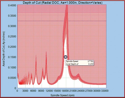
The diagram on the right illustrates this. Across the range of spindle speeds seen here, the peaks indicates where this particular machine and tool setup is capable of more productive cutting. The crosshatched area shows where chatter occurs. Thus, stable cutting with a particularly large depth of cut is possible at 17,792 rpm, even though nothing like that same level of heavy milling would be possible if the machine ran just a little faster or slower than this value. The shop that isn’t aware of this magic speed has no idea what its machining center actually can do.
In fact, the shop might also have no idea what its tools can do.
Tool Strangeness
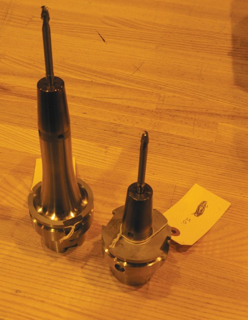
Differences in tool performance reveal one more potentially surprising aspect of high speed machining. When BlueSwarf tap-tested Warner Robins’ oldest high speed machining center, it made the discovery illustrated in the photos at then end of the series above. Typically, shorter tooling provides for more stable milling—but not always. On this particular machine, the system was actually found to be more stable, and capable of heavier depths of cut, when using the longer of the two tool setups shown in the photograph. The more flexible tool permits higher metal removal rates on this particular machine.
The shop used the machine for years without knowing this. The machine performed well, but the information certainly would have helped. For all those years, the machine could have performed better. Running without this valuable information was like making do with less, the shop says—or like running with that machine tool’s potential output and quality both dialed down.
Related Content
Inverting Turning and Five-Axis Milling at Famar
Automation is only the tip of the iceberg for Famar, which also provides multitasking options for its vertical lathes and horizontal five-axis machine tools.
Read MoreHow to Mitigate Chatter to Boost Machining Rates
There are usually better solutions to chatter than just reducing the feed rate. Through vibration analysis, the chatter problem can be solved, enabling much higher metal removal rates, better quality and longer tool life.
Read MoreOrthopedic Event Discusses Manufacturing Strategies
At the seminar, representatives from multiple companies discussed strategies for making orthopedic devices accurately and efficiently.
Read MoreHigh RPM Spindles: 5 Advantages for 5-axis CNC Machines
Explore five crucial ways equipping 5-axis CNC machines with Air Turbine Spindles® can achieve the speeds necessary to overcome manufacturing challenges.
Read MoreRead Next
Building Out a Foundation for Student Machinists
Autodesk and Haas have teamed up to produce an introductory course for students that covers the basics of CAD, CAM and CNC while providing them with a portfolio part.
Read More5 Rules of Thumb for Buying CNC Machine Tools
Use these tips to carefully plan your machine tool purchases and to avoid regretting your decision later.
Read MoreSetting Up the Building Blocks for a Digital Factory
Woodward Inc. spent over a year developing an API to connect machines to its digital factory. Caron Engineering’s MiConnect has cut most of this process while also granting the shop greater access to machine information.
Read More

