Share


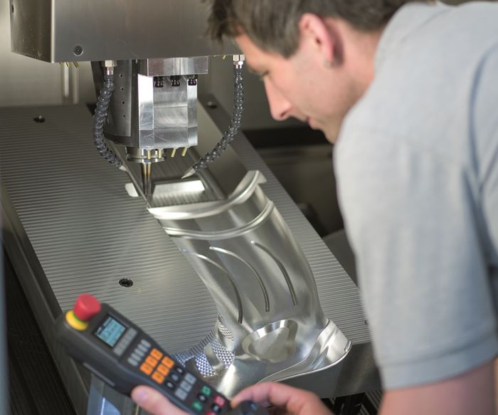
Control over how a tool meets metal is often left solely to CAM system output that has been translated (often imperfectly) into G code by a postprocessor. That might be enough to produce the part to specification, but not necessarily as efficiently as possible, particularly with sophisticated five-axis equipment.
So says Gisbert Ledvon, business development manager for Heidenhain Corp.’s TNC line of computer numeric controls (CNCs). Whereas CAM software is generally designed for flexibility and applicability across a variety of equipment, the CNC provides a direct interface with a particular machine tool’s axis drives, scales and other mechanical elements, he explains. Some of the finer fine-tuning facilitated by the more intimate CNC-to-machine connection can even be performed in real time, whether to avoid the need for additional programming or to enhance toolpath strategies programmed well in advance.
In short, the greater a shop’s awareness of how features native to the CNC can improve metal removal rates while reducing strain on spindles and cutting tools, the better its ability to take full advantage of the machine capability. Mr. Ledvon cites the following as examples of Heidenhain CNC functionality that, when the application is right, can help improve material removal rates while reducing strain on spindles and cutting tools:
Active Chatter Control (ACC)
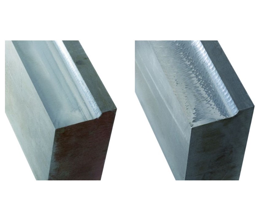
During roughing operations, this capability leverages signals from the machine’s feed drives to detect chatter, a form of self-amplifying vibration that results when the workpiece resonates at a different frequency than the spindle and the tool. ACC then manipulates the drives to create a damping effect. This reduces the load on tool and machine alike to facilitate more aggressive parameters, improved tool life, a smoother finish and a higher material removal rate.
However, this doesn’t happen automatically, in the background. The user must actively arm ACC and define the frequency range in which it operates. The value must be below the tool’s engagement frequency and no more than 100 Hz, and different parameters can be set for different tool geometries. Prior to that, the machine tool builder will have configured the system for the unit’s specific harmonic structure, assuming that builder offers ACC as a standard or optional CNC feature in the first place. Mr. Ledvon says ACC is most useful for precise, complex workpieces, particularly those that require smooth finishes on surfaces with too little stock for dedicated finishing operations.
Adaptive Feed Control (AFC)
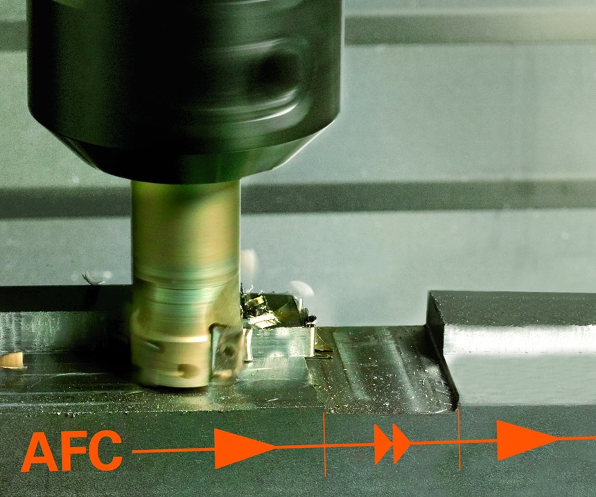
As the name implies, this functionality optimizes the feed rate according to cutting conditions in real time. It does so by continuously monitoring spindle power, reducing and even stopping the feed as power increases beyond a certain point (an indication of tool wear) and increasing the feed as power decreases (an indication of less stock or otherwise easier cutting conditions). More common than ACC, AFC is similar in that it requires attention from the user, Mr. Ledvon says. In this case, the user must set the minimum and maximum spindle power, determining the latter via a teach-in cut.
Granted, there are other means of optimizing feed rates that don’t require teach-in cuts. Nonetheless, working directly through the CNC offers distinct advantages when work is unpredictable. Mr. Ledvon says he cites the example of a cast part, which might feature variations in stock levels that are not reflected in the part program. In this case, adjusting feed based on spindle load can provide savings beyond any pre-machining optimization. Repairing injection molds (say, by using a portion of the original part program to cut weld-repair stock from a specific area of a cavity) is another example of an application in which the precise amount of stock to machine may be unknown. “If you have a last-minute change on the part, or you hold it a little bit differently, or you are not engaging the tool as perfectly as you thought, tapping into AFC can help,” he says. He adds that parts initially produced via additive manufacturing don’t always match the model precisely, either.
3D Tool Compensation
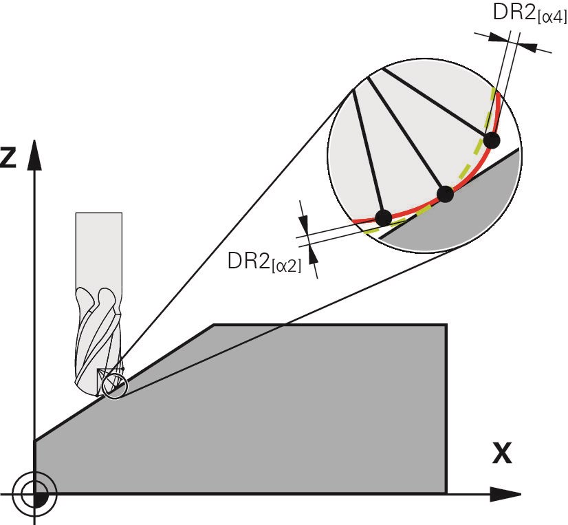
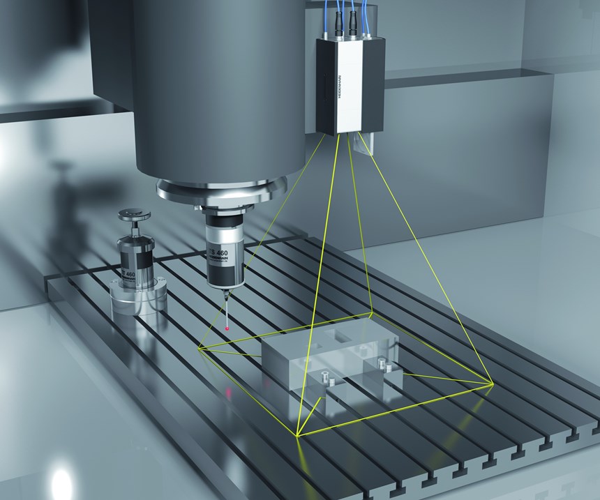
Effective cutting radii on ballnose, bullnose or similar cutters present another example in which data in the CAM program might not precisely match the reality on the shop floor. Whether due to wear, the angle of the tool against the workpiece, or a tolerance band between the actual dimension and the supplier’s catalog specification, compensation is not always based on the correct values. This CNC feature helps users obtain more accurate data by measuring specific points of the cutting tool edge/radius with an on-machine laser. More accurate data translates to higher quality blends and smoother surfaces, Mr. Ledvon says.
Global Settings
Mr. Ledvon cites two examples of improvements possible via adjustments to the CNC’s global settings. First, users can angle the tool in real time as machining proceeds. Returning to the example of injection mold repair, he says tilting a cutter by just a few degrees can often provide smoother blends between respective features or areas of the part. Although this requires a sufficiently skilled and knowledgeable operator, features like AFC and 3D tool compensation can help ensure stability.
Second, global settings adjustments can enable users to apply the same tool paths to identical parts arranged in different configurations. “Normally, when you change something from X plus to X minus, the program might look at things differently and you’ll see it on the part,” he explains. As an example, he cites automotive rear-view mirrors, which come in left- and right-hand versions that typically must look exactly alike. Rather than generate different programs for the two parts, the same tool paths can be mirrored instantly from one to the other, with all adjustments necessary to account for the new orientation. He adds that this capability can help streamline machining of larger parts that might need to rotate within the workzone for spindle access.
Load Adaptive Control (LAC)
Parts are not always perfectly centered on five-axis machine worktables, and even the most symmetrical setups become less so as material is removed. Whatever the cause of imbalance, chatter is the likely result, unless that imbalance can be countered dynamically. This is the purpose of LAC, which conducts a brief cycle to determine the mass and inertia of the setup. Machining parameters are compensated accordingly. These cycles can be called up in the CAM program or initiated as needed by the operator, Mr. Ledvon says.
The list above is anything but comprehensive. For instance, CNC kinematic cycles can significantly reduce time required for axis calibration. Another capability, visual setup control, uses cameras to compare setups to an ideal reference and automatically highlight any discrepancies, which might range from missing fixtures and incorrect workpiece orientations to hand tools accidentally left within the workzone. Some controls even facilitate turning operations on five-axis machining centers by locking the spindle and spinning the work. At the most recent EMO event in Germany, Heidenhain released a State Monitor function, which is designed to provide an accessible means of shops for all sizes to pull analytics from every machine in a facility with a TNC-model control (Mr. Ledvon says broader interoperability is a future goal).
Whatever the manufacturer of the CNC, offerings are likely to be broad when it comes to efficiency- and quality-enhancing functionality. Indeed, some of that functionality is likely to be superfluous for any given user. Nonetheless, Mr. Ledvon insists education about the CNC is particularly important in an era when talent is hard to find and decision-making increasingly occurs away from the shop floor. This is particularly true for the kinds of five-axis applications described in this article, he adds. “We want to make sure that when someone gets an expensive five-axis machine, they’re not missing out on all the bells and whistles.”
Related Content
Inside a CNC-Machined Gothic Monastery in Wyoming
An inside look into the Carmelite Monks of Wyoming, who are combining centuries-old Gothic architectural principles with modern CNC machining to build a monastery in the mountains of Wyoming.
Read MoreLean Approach to Automated Machine Tending Delivers Quicker Paths to Success
Almost any shop can automate at least some of its production, even in low-volume, high-mix applications. The key to getting started is finding the simplest solutions that fit your requirements. It helps to work with an automation partner that understands your needs.
Read MoreHow to Mitigate Chatter to Boost Machining Rates
There are usually better solutions to chatter than just reducing the feed rate. Through vibration analysis, the chatter problem can be solved, enabling much higher metal removal rates, better quality and longer tool life.
Read MoreInverting Turning and Five-Axis Milling at Famar
Automation is only the tip of the iceberg for Famar, which also provides multitasking options for its vertical lathes and horizontal five-axis machine tools.
Read MoreRead Next
Registration Now Open for the Precision Machining Technology Show (PMTS) 2025
The precision machining industry’s premier event returns to Cleveland, OH, April 1-3.
Read MoreBuilding Out a Foundation for Student Machinists
Autodesk and Haas have teamed up to produce an introductory course for students that covers the basics of CAD, CAM and CNC while providing them with a portfolio part.
Read MoreSetting Up the Building Blocks for a Digital Factory
Woodward Inc. spent over a year developing an API to connect machines to its digital factory. Caron Engineering’s MiConnect has cut most of this process while also granting the shop greater access to machine information.
Read More


