
Closed-Loop Gear Production
A familiar concept is now gaining serious traction, enabling manufacturers to develop closed-loop cells that automatically match the finished product to design concept goals.
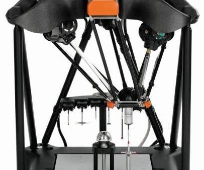
Renishaw’s Equator gaging system scans gears following machining on the Mazak Integrex i-100ST. The scan data is then fed back into Dontyne’s Gear Pro software for adjustments, closing the loop on this system.
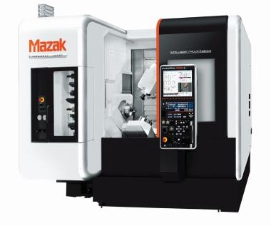
The centerpiece of a single-setup gear production system, Mazak’s Integrex i-100ST milling and turning center provides features conducive to specialty gear cutting.
Share


Consider the many aspects of gear production—hobbing, form cutting, critical surface finishing, skiving and scudding, all likely involving specialty tooling running on specialty machines. No wonder even seasoned milling and metalworking professionals view gear cutting as some mysterious island with its own secret ways and language.
However, advances in metalworking hardware, software and inspection are casting new light on gear production, specifically with the development of closed-loop cells that can adjust and produce high-precision products with limited operator input.


Fast Track Production
“Gears are subtle,” says Mike Finn, national applications engineering manager at Mazak, which is based in Florence, Kentucky. From contouring errors to tool deflection to bending moment resistance, there are many opportunities in production to lose accuracy or increase processing time and effort. Together with gear design software developer Dontyne Systems (Newcastle upon Tyne, United Kingdom) and metrology technology provider Renishaw Inc. (with U.S. operations located in Hoffmann Estates, Illinois), Mazak is offering a closed-loop gear production system centered on its Integrex i-100ST multi-axis milling and turning center.
With the “S” designation standing for a second turning spindle and the “T” meaning the machine has a lower turret for milling on either one, the machine tool is an appropriate centerpiece for single-setup gear machining. With all the advantages of modern machine tool construction, such a milling and turning center has the rigidity, heat displacement, vibration control and multi-axis travel that specialty gear cutting requires. Furthermore, where high-volume contracts are required to justify investment in specialty machines and tooling, a multitasking machining center can cut gear sets efficiently at low volumes and speed time to market.
At a recent Mazak open house, Mike Fish, co-director at Dontyne Systems, described how his company’s Gear Design Pro software, part of its Gear Production Suite, integrates with the Integrex. According to Mr. Fish, the biggest selling aspects of his firm’s software are ease of use and closer integration of gear design with manufacturing.
“With access to points during manufacture not only for machine tools, but also inspection equipment, our software can not only design, but optimize and problem-solve,” he said. “Many companies state the Gear Production Suite also works very well alongside larger gearbox design packages already in-house, creating a fast track option for certain projects or tasks requiring fast turnaround.”
With the expected modules for designing and analyzing helical, spur and bevel gears, the Dontyne software is a deep dive into making gears unique to their function, not to their production capability. In bevel gears, for instance, starting with a generic bevel means the geometry is not specific to a machine process, but is the true theoretical gear form, with full-line conjugation between components without any virtual back plane approximations. Spiral types can be defined as straight, logarithmic (equal angle), circular or involute. Typical modifications such as profile crowning, face crowning and slope can be applied to modify the load-bearing pattern shape and position to job requirements.
Analysis options abound, such as gear tooth deformation under load, bearing load patterns and a GATES model, which stands for Gear and Transmission Error and Stress. Graphs and reporting screens show where surface modifications can be applied to minimize transmission errors under load, reducing noise and vibration. Reduced stresses means more power.
Design Optimizes Production
Once all the analysis is done and minimum/maximum tolerances on the chosen design are established, all this data is fed to the machine tool for optimizing machine conditions and appropriate tool selection. Screens show live results as machining occurs, using existing machine settings and tool conditions. For example, as tooth thickness is reduced by sharpening along the X axis, a blue line shows how much diameter reduction is left to maintain force balances. Users can click on the diagram at any time to create optimum profiles.
If multitasking machining is the centerpiece, and specialized gear design and analysis software is the heart, the inline Equator gaging system from Renishaw closes the loop. Following machining, a gear is transferred into the CMM, where a scanning probe quickly gages the part. Data is fed automatically back into the Gear Pro software for reposting to the machine tool to update tool offsets and make other adjustments. Pitches, profiles, flanks and other features are compared to standards or master part data. If tolerances are maintained, the process continues; if not, adjustments are made. Furthermore, averages can be created from multiple measurements and saved for generating more precise masters for future programs.
The traditional gear cutting process can be summarized as “Cut it, leave a little material, check it, pre-finish, check it, finish and check it again.” Closed-loop gear machining can take such an intensive approach and not only reduce it from days to hours, but also make it traceable, repeatable and as close to error-free as possible. This can bring a dark art into the light for more shops.


Related Content

Digitalization and Done-In-One Reign Supreme at BIEMH 2024
European manufacturers may have a different balance of markets than their U.S. counterparts, but the practical challenges they must overcome are often similar — as are the solutions.
Read More
Industry Analysis: Machining Semiconductor Components
With many machine shops anticipating long-term growth in demand from the semiconductor industry, it is worth the time to heed the advice of manufacturers who have already been servicing this end-market for years.
Read More
TTI Brings Specialty Gear Production In-House with Multiaxis Machining
By investing in a 3+2-axis machine and utilizing simulation software for diagnostic checks, Techtronic Industries turned a four- to ten-week lead time into a one- to two-week lead time.
Read More
Integration, Automation and Green Tech Highlight JIMTOF 2022
Known as one of the largest machine tool trade shows in the world, the Japan International Machine Tool Fair (JIMTOF) has a reputation for being a machining technology show more than a machine tool sales event. And this year’s show in Tokyo — the first in-person Japanese machine tool trade show in four years — did not disappoint.
Read MoreRead Next

Closing the Loop
Gathering information is worth it only if it’s put to practical use. Applying measurement data to streamline spiral bevel gear making clarifies the true value of the closed-loop process.
Read More
Setting Up the Building Blocks for a Digital Factory
Woodward Inc. spent over a year developing an API to connect machines to its digital factory. Caron Engineering’s MiConnect has cut most of this process while also granting the shop greater access to machine information.
Read More
Registration Now Open for the Precision Machining Technology Show (PMTS) 2025
The precision machining industry’s premier event returns to Cleveland, OH, April 1-3.
Read More