Share


Shops can benefit in a number of ways by broaching on a CNC lathe. Locking a lathe’s spindle and driving a broaching tool in and out of a workpiece to create keyways and slots increases the number of operations that can be performed in a single chucking on a single machine. This improves feature-to-feature accuracy, reduces the amount of time for handling and setup and eliminates the need for specialized broaching equipment.
Tools with brazed or replaceable carbide inserts are commonly used for such broaching operations. The latter version offers an advantage in that the insert — not the entire tool — can be replaced after it becomes worn. That way, the tool body can remain installed in the lathe’s turret during insert replacement, making it unnecessary to re-zero the tool after a new insert is installed.

This hardened Inconel part required five internal, blind-broached slots each oriented with a positional tolerance of only 0.004 inch relative to the other slots. (Photo credits: Powill Manufacturing)
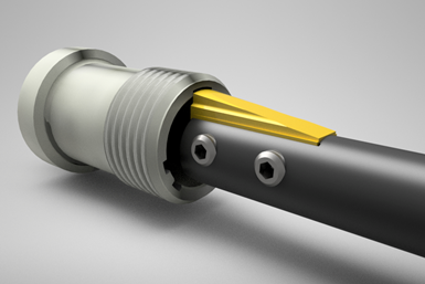
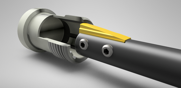
In fact, Phoenix, Arizona’s Powill Manufacturing has found value in an indexable-insert-style broaching tool for CNC lathes which provides two cutting edges per carbide insert. The patented broaching tool system from CNC Broach Tool is said to be the industry’s first indexable-insert-style broaching tool, providing two cutting edges per TiN-coated, micro-grain carbide insert. Once one insert edge becomes worn, a machine operator removes two set screws securing the insert to the tool body and flips the insert around to present the second cutting edge. This design not only decreases tooling cost, but also increases tool life and performance, according to CNC Broach Tool.
Kevin Wolfe, Powill Manufacturing general manager, says this tooling system offers a dependable solution for creating blind-hole broached slots in heat-treated Inconel aerospace parts.
“CNC Broach Tool has given us a significantly shorter lead time than other suppliers,” Wolfe says. “Its carbide inserts last longer in Inconel and provide a better finish than high-speed steel options.”

For this application, the broaching operation was performed using a feed rate of 300 ipm at a depth of cut of 0.001 inch per pass.
Powill Manufacturing had the opportunity to quote a hardened Inconel part which required five internal, blind-broached slots. These slots needed to be oriented with a tight positional tolerance of only 0.004 inch relative to the other slots. Since the slots were blind, they couldn’t be broached in a conventional broach machine and the tight tolerance would be nearly impossible to hold once unclamped from the spindle. The orientation and positional tolerance definitely couldn’t be held consistently on a shaper or a manual push broach.

Since the slots were blind, they couldn’t be broached in a conventional broach machine.
The shop’s engineering team faced a challenge, as there were very few options available to create this feature. However, the team found a solution using CNC Broach Tools custom ground carbide inserts. Powill Manufacturing was awarded the contract and its decision to use this type of broaching tool system has resulted in high-quality parts due to the precision and repeatability of the broaching process in its CNC lathe. After some experimentation, the shop discovered that the optimal broaching parameters for this Inconel application was a feed rate of 300 ipm with a depth of cut of 0.001 inch per pass.
Powill Manufacturing chose to keep the broaching process of this complicated part in-house.
Before discovering CNC Broach Tools, Powill Manufacturing faced an unrelenting challenge in broaching blind holes, forcing them to outsource parts to external suppliers. Relying on subcontractors, however, carries significant risks, such as lead time, quality and high cost. To reduce this risk, Powill Manufacturing chose to keep the broaching process of this complicated part in-house and perform the operation on one of its CNC lathes.
Broaching Tips for CNC Machines
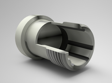
CNC Broach Tool offers the following advice for broaching on CNC lathes: mount its tools in a boring bar sleeve, specifically split sleeves from Rovi Products, which provide an accurate and solid connection 360-degrees around the tool shank. Although solid sleeves can work as well, they are not as accurate or rigid when they become worn, and any play in the sleeve can cause tool chatter or deflection. If solid sleeves are a shop’s choice, it’s recommended to use units from Machine Tool Accessories and Manufacturing Co. that have two pairs of set screws 90-degrees apart, offering three-line clamping (the line formed by the two pairs of set screws and the opposite side of the sleeve bore).
It is also important to dial in the tool’s orientation to be inline with the lathe’s X axis. This can be done by removing the insert from the toolholder and using a gage block that fits into the insert pocket. After lightly tightening the tool set screws to simply to hold the gage in place, a dial indicator can be used. The block should be dialed in to 0.0005 inch. The front diameter of the tool should then also be dialed in to that same specification for the Y axis. After that, the gage block is removed and replaced with the insert.
When using a broaching tool in a CNC milling machine, a hydraulic toolholder is preferred. If this is not an option, a solid toolholder with a minimum of two set screws will work as well. It is important to use a solid back stop behind the tool to prevent it from pushing back in the toolholder. To help ensure rigidity, Cat 40/50/60 or Big-Plus dual-contact toolholders are recommended. Tool orientation must be dialed-in relative to either the mill’s X or Y axes using a gage block. This is similar to the process for lathes, yet uses an M19 code to orient the tool.
For shops that are new to this type of tooling system, CNC Broach Tool offers a G-code programming generator available on the company’s website. With it, users can automatically create the G code to run the broach tools on CNC lathes or mills. After choosing machine type, users pick the type of tool and enter values for features such as bore diameter, keyway width, radial depth, depth of cut, feed rate and Z-axis start and end points. Once generated, the G code can be copied and pasted into the part program.
Related Content
Machine Monitoring Boosts Aerospace Manufacturer's Utilization
Once it had a bird’s eye view of various data points across its shops, this aerospace manufacturer raised its utilization by 27% in nine months.
Read MoreIncreasing OEM Visibility to Shopfloor Operations for the Win
A former employee of General Motors and Tesla talks about the issues that led to shutdowns on factory lines, and what small- to medium-sized manufacturers can do today to win business from large OEMs.
Read MoreSandvik Coromant Inserts Provide Stable Turning of Aerospace Components
The new insert grades GC1205 and GC1210 cover a large application area within last-stage machining and intermediate-stage machining when turning aerospace engine components.
Read MoreBavius Technologie Appoints New President, Schedules Technology Showcase
Roy D. Cripps will lead the team at Bavius as it aims to expand its current business in aerospace structures and develop new market segments. Additionally, the company will showcase its technology during an open house event on June 11.
Read MoreRead Next
Registration Now Open for the Precision Machining Technology Show (PMTS) 2025
The precision machining industry’s premier event returns to Cleveland, OH, April 1-3.
Read MoreSetting Up the Building Blocks for a Digital Factory
Woodward Inc. spent over a year developing an API to connect machines to its digital factory. Caron Engineering’s MiConnect has cut most of this process while also granting the shop greater access to machine information.
Read MoreBuilding Out a Foundation for Student Machinists
Autodesk and Haas have teamed up to produce an introductory course for students that covers the basics of CAD, CAM and CNC while providing them with a portfolio part.
Read More


