Artificial Intelligence from an Intelligent Amplifier
With intelligent amplifiers providing measuring capabilities and easier setups, it’s easier than ever to understand what is going on in the manufacturing process in real time.
Share


Hwacheon Machinery America, Inc.
Featured Content
View More


Autodesk, Inc.
Featured Content
View More


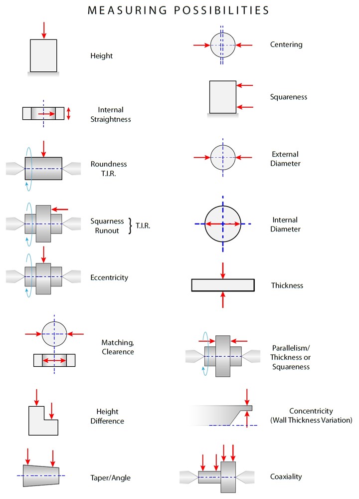
Many basic dimensional gaging applications are actually just variations of tools for measuring length, generally in one of four basic dimensions: height, depth, thickness or diameter. Relational or geometric gaging applications are nearly as straightforward, conceptually. Measuring qualities like roundness, concentricity, symmetry, eccentricity, straightness, squareness, taper, parallelism or distance between centers is usually a matter of measuring a few dimensional features, then doing some simple calculations.
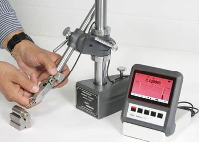
Today most amplifiers or PC-based amplifier systems are quite intelligent, so why not let the gage do the calculations? Even simple benchtop gaging amplifiers can measure two or more dimensions simultaneously and manipulate the readings through addition, subtraction or averaging. (Air gaging can also be used in many of these applications, but for simplicity, we'll limit this discussion to electronic gage heads.) A wide range of relational characteristics can be measured with just one or two gage heads; it’s basically a question of setting them up in the right configuration and making sure that the fixture is capable of maintaining a precise relationship between the part and the gage heads.
With a little imagination, you can combine several related and/or independent measurements into a single fixture to speed up the gaging process. For example, concentricity is a relatively complex measurement often requiring a form measuring system or coordinate measuring machine (CMM). By taking multiple traces or with extensive scanning, a true concentricity analysis can be made. However, making all these calculations can take a lot of time and cause a delay between when the part is machined and the receipt of very precise results. This is good for part analysis, but the delay can cause production bottlenecks. It is helpful, therefore, to strike a balance between a high-end precision measurement and one that simply provides a good indication of quality right at the point of manufacture.

A fixture gage probe layout for performing a concentricity measurement.
The image here shows a fixture gage probe layout for doing a concentricity measurement using eight probes in a static test of concentricity. The equation for concentricity looks at probes that are measuring diameters. For example, in this diagram, probes P1 and P2 can be used for measuring a diameter. They also can be used to find the center of the small shaft diameter, while P3 and P4 are used to find the same shaft diameter center but at 90 degrees relative to the first calculation. The same is done on the large-diameter end of the shaft. Then, through the calculations, a comparison is made between one center and the other for the concentricity relationship. It’s not as pure as a concentricity check on a form system — but by using an amplifier system with a little computing intelligence, an indication of concentricity can be provided instantaneously. In a high-volume production environment, this can save hours of daily production time.
The calculation shown here is made for concentricity, but all the probes are capable of providing other important results as well. For example, the two sets of probes for the small-end diameters can be measured and recorded and the difference “roundness” can be calculated all at the same time.
Using these principles, custom fixture gages can be designed for a wide range of applications, or existing gages can be modified for additional capabilities. Electronic gage heads (i.e., transducers) and air probes are available in many configurations and sizes, some of them small enough to permit simultaneous measurements of very closely spaced part features. And with intelligent amplifiers providing measuring capabilities and easier setups, it’s easier than ever to get more measurement results at the point of manufacture to better understand what is going on in the manufacturing process in real time.

A range of relational characteristics can be measured with just one or two gage heads if you set them up right and make sure the fixture can maintain a precise relationship between the part and the gage heads.
Before you begin, you'll need to check the manufacturer’s specs for gage head dimensions, accuracy and range. Even if you don’t want to build the gage in house, you can use these ideas to design a “schematic” that can inform your discussions with custom gage makers.
Related Content
How to Calibrate Gages and Certify Calibration Programs
Tips for establishing and maintaining a regular gage calibration program.
Read MoreProcess Control — Leveraging Machine Shop Connectivity in Real Time
Renishaw Central, the company’s new end-to-end process control software, offers a new methodology for producing families of parts through actionable data.
Read More6 Machine Shop Essentials to Stay Competitive
If you want to streamline production and be competitive in the industry, you will need far more than a standard three-axis CNC mill or two-axis CNC lathe and a few measuring tools.
Read MoreOrthopedic Event Discusses Manufacturing Strategies
At the seminar, representatives from multiple companies discussed strategies for making orthopedic devices accurately and efficiently.
Read MoreRead Next
Amplifiers: More than Just Readout Devices
Tapping into built-in functions can increase efficiency and enhance productivity.
Read MoreBuilding Out a Foundation for Student Machinists
Autodesk and Haas have teamed up to produce an introductory course for students that covers the basics of CAD, CAM and CNC while providing them with a portfolio part.
Read More5 Rules of Thumb for Buying CNC Machine Tools
Use these tips to carefully plan your machine tool purchases and to avoid regretting your decision later.
Read More


