A Solid Footing
When a manual pattern maker stepped up to CNC machining, he needed a simple way to write tool paths for his complex patterns. He found it. He also found a source of revenue he never anticipated.
Share


Superior Pattern Works president Ted Keen has always made patterns using solids. For most of his career, these were solid pieces of wood. But after purchasing his first computer numerical control (CNC) machining center earlier this year, he began to spend the majority of his productive time working with the virtual solids in a CAM (computer-aided manufacturing) system based on solid modeling.
The pattern work invariably involves intricate shapes, rich in detail. Still, Mr. Keen shied away from CAD/CAM systems offering high-end design capabilities. A pattern maker doesn't need to be a designer, he points out. What this pattern maker needed instead was a simple, efficient system for converting his customers' designs—most of which arrive as hard-copy drawings—into machining center tool paths.
He decided that only solid modeling would let him be productive immediately. It didn't require him to learn a new method of pattern making. For example, he didn't have to become proficient at reproducing the design from points and lines. Instead, solid modeling—in his case, using Gibbs and Associates' Virtual Gibbs—lets Mr. Keen, a CAM newcomer, build pattern designs using a PC in much the same way that he would otherwise build the pattern itself. That is, by cutting and combining solid forms.
The Move To CNC
Ted Keen has worked in foundries all of his life. He incorporated his Houston, Texas, pattern company in 1985, running it out of his home until six years later, when he moved into the shop where he and his 13 employees now work. His customers come primarily from the oil industry. In general, "if it's not pumps, it's valves," he says—though he also strives always to maintain one or two customers outside of Texas, so he is not entirely hostage to the highs and lows of the oil market.
Mr. Keen learned pattern making—historically a woodworking exercise—in shops that were "full of skilled pattern makers." But now those craftsmen are disappearing, making the remaining ones more and more costly to employ. "Salary and benefits are just about the biggest expenses I contend with," he says. In fact, these costs have grown so high, they have compelled him to move beyond the manual craft he has always known.
Aiming to build his business without adding more pattern makers, Mr. Keen sought a way to automate much of what the pattern maker does. That is, create a physical pattern from a conceptual design. The combination of CAM software and CNC machining fit this requirement.
Mr. Keen now does most of the "manual" work for many patterns at a PC. If he can't import a customer's computer-aided design (CAD) file, which is his preferred approach, then he constructs a representation of the hard-copy design by manipulating virtual solids in his CAM software. He departs from his customer's design only where his knowledge of the behavior of cooling metal demands it—to allow for shrinkage, for example, or to avoid a casting defect that the part geometry might otherwise encourage.
From there, the process requires little attention. The software translates the design into numerical control (NC) code, based on his input for tool dimensions, machining parameters, machining routines, and other variables. Mr. Keen verifies this code by watching animation of the tool paths created through the software's rendering function. Satisfied that the program will accurately produce the part, Mr. Keen sends it to the machining center, and lets the job run while he moves on to the next project.
Economics Of Upgrading
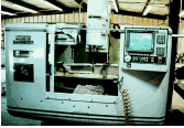
Mr. Keen purchased his first CAM software earlier this year. He did so at about the same time that he purchased his first CNC machining center, a Milltronics vertical with 34 inches of X-axis travel.
He had considered CNC machining as a pattern making tool for about three years prior to this. However, he always suspected that skilled manual labor could produce his most complex designs more efficiently than CNC machining. That assumption changed the day he saw a shop machining a one-piece turbine rotor from solid metal. "If the machining center could do that, I knew it could do my jobs, too," he says.
His next concern was how to justify such a machine. What if he couldn't bring in enough new work to pay for the investment?
"I finally told myself that if I couldn't get the pattern work, I could at least take in enough conventional machining jobs to make up the difference," he says.
However, that scenario overlooked a third source of revenue—rapid prototyping. Only after the purchase did Mr. Keen discover that his ability to turn intricate designs into physical models quickly—via the CAM software—made his services attractive to design engineers who want not foundry patterns, but prototypes of their designs. That is, models that they can hold in their hands, and examine.
These prototype jobs, which Mr. Keen runs in machinable plastic, now account for 70 percent of the work he performs on his Milltronics machine.
The irony is that this workload has driven him to hire more people. The new employees don't help him feed the CNC machine, but instead make up for the pattern making capacity now lost while Mr. Keen works on rapid prototyping jobs.
Skipping School
Two trends affecting CAM software help explain Superior Pattern Works' seamless move from manual pattern making into complex, profitable CNC machining. One is improved PC processing power. The other is lower prices for solid modeling technology. Both trends together have helped to make sophisticated CAM software more accessible to the novice user—more accessible to own, and more accessible to operate because of the intuitive interface. By extension, this also makes CNC machining more accessible in applications where the parts demand complex programs that only CAM could generate. Applications like pattern making.
Mr. Keen—an expert in foundry work, not machining—had never before programmed an NC machine tool as recently as one year ago. However, he and Richard Holt, another company pattern maker who now uses the software, were "already making simple patterns within an hour of being introduced to solid modeling," Mr. Keen says. Both men were using CAM profitably for the shop's most complex work not long after that, and as late as five months after purchasing the software, both had yet to attend one of the vendor's classes to learn how to use it.
Instead, they taught themselves, using built-in help functions and telephone support from Gibbs and Associates. "That, plus Jason Heyse of Texas Offline [the software's local sales rep] spent a little time with us," Mr. Keen explains.
For this relatively painless mastery of CAM, Mr. Keen credits solid modeling's approach to building geometries. Instead of requiring the user to construct each feature of the model as a wireframe or collection of surfaces—that is, one point or surface at a time—solid modeling lets the user work with virtual solid bodies. The result is like using building blocks instead of an erector set.
To create a solid model, the user starts with a simple body. This can be a cube or sphere, or an extrusion of a simple shape. This body is then modified using other simple bodies, which might be added to, subtracted from, or intersected with the evolving model.
Each such operation may create any number of new faces, and affect any number of surfaces. However, the user is spared from having to manipulate the model at this level of detail. Solid modeling thus streamlines and automates much of the traditional CAD modeling process.
Solid modeling by itself doesn't offer a practical way to construct fluid surfaces with complex contours (though the Gibbs software, for example, does offer surfacing capability for importing and creating these geometries). However, where the design is built from geometric shapes that are elementary enough for a draftsman's dimensioned drawing to describe them, solid modeling offers a streamlined way to create this design at a PC.
Solid modeling and CNC together have taken Mr. Keen's shop further than he once expected it would go. He used to be concerned about CNC machining being impractical for the intricate parts his shop takes on. But now, solid modeling and CNC routinely let the shop produce patterns that could never have been produced by hand.
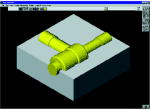
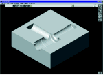
The intricate and precisely detailed pattern on the computer screen in the photo on page 90 is one example. "Working by hand, we could never have held the accuracy this part required," says Mr. Keen.
However, the machining center can hold this accuracy. And using the solid modeling CAM software, Mr. Keen went from dimensioned drawing to the NC program for this part within six hours.
CAM Leverage
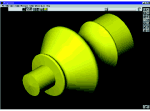
Whether or not it is based on solid modeling, CAM software of some kind is a must for CNC machining of foundry patterns. The cast parts the patterns represent are at least contoured, if not complex. A pattern for a cast iron flower pot—commissioned by an artist in Mr. Keen's area—illustrates why CAM is needed (see illustration at right). How could the tool paths for such an organic shape be defined through manual programming?
Mr. Keen doesn't know. He created the shape in his CAM software by drawing a line, rotating it to define the virtual solid, and from there generating the machining program. All of the PC work together took him about two hours.
However, programs generated from Mr. Keen's models are generally even more complex than the one this part required. They take a long time for the machining center to run, simply because of the intricate detail. So on an average of three nights out of every five, Mr. Keen leaves the machining center unattended to machine a part overnight. One pattern required the machine to run unattended for 40 hours straight over a weekend.
Mr. Keen admits to some initial trepidation about leaving the machine alone like this. But then he realized: "If the machine is going to wreck, it's going to wreck whether I'm standing there or not. So there's really nothing to lose."
Still, CAM is good for more than just writing the long programs for these complex jobs. It also makes routine aspects of pattern making simple to achieve. These include:
- The stock envelope. This is necessary to expand a pattern's volume in anticipation of metal shrinkage. Stainless steel, for example, requires a 3.6 percent shrinkage envelope. On a manual pattern, this envelope would be applied by covering the pattern with a layer of wax. But in CAM software, adding a consistent stock envelope is just a matter of automatically scaling up the dimensions of the design.
- Lettering. The part number, pattern number, and even the customer's logo might be pasted onto a wooden pattern. In CAM software, these figures often can be imported as data files and added automatically.
- Design changes. "We get in-process design changes on about 40 percent of our jobs," says Mr. Keen. After all, his jobs often involve new designs—parts his customers have never before produced, let alone incorporated into a finished product. However, the manual method of pattern making left little room to salvage any pattern that a design change has rendered obsolete. The casting from the superseded pattern might be used to make the pattern for the revised design, but only if the revision is so convenient that a pasted-on feature—or perhaps a cut with a mill or boring bar—could make the required change. By contrast, a CAM software model offers much more freedom to modify the design without reinventing it.
-
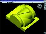
Related parts. The best example of this is a mirror-image part. Most CAM software systems let the user mirror a design with just a simple series of commands. Mr. Keen discovered the usefulness of this feature on a job for mirror-image patterns, which he quoted to the customer just before he purchased the CAM software. After the software arrived, he used its mirroring function to let one model serve as the basis for the other. Mr. Keen thus discovered that he could do the job profitably for about 70 percent of the price he quoted to the customer. (The model that is featured in the lead illustration for this article is another example of a design that Mr. Keen later mirrored to produce a related pattern.)
No Guesses
But one of the most important advantages of pattern making via CAM software and CNC machining is that it can eliminate any margin for misunderstanding. That's why Mr. Keen wishes all of his customers could give him their designs the way about 30 percent of them do now, as CAD files in IGES format.
"There's so much educated guesswork in reading a dimensioned drawing, and a lot of room for misinterpretation," he says. "But when the customer provides an IGES file, he can't say he didn't get what he asked for."
But achieving purely electronic customer input is a far-reaching goal. In the short term, Mr. Keen has other plans. One of these is to purchase more CNC machining capability. This will include a CNC lathe, as well as a second Milltronics machining center—this one with a larger machining envelope than the first.
"And I want to get a laptop computer," he says. "When I visit customers, I'll show them their own solid models, and show them the rendering of the machining cycle right there on the screen. I think that will really impress them."
Related Content
How this Job Shop Grew Capacity Without Expanding Footprint
This shop relies on digital solutions to grow their manufacturing business. With this approach, W.A. Pfeiffer has achieved seamless end-to-end connectivity, shorter lead times and increased throughput.
Read MoreThe Power of Practical Demonstrations and Projects
Practical work has served Bridgerland Technical College both in preparing its current students for manufacturing jobs and in appealing to new generations of potential machinists.
Read MoreTips for Designing CNC Programs That Help Operators
The way a G-code program is formatted directly affects the productivity of the CNC people who use them. Design CNC programs that make CNC setup people and operators’ jobs easier.
Read MoreERP Provides Smooth Pathway to Data Security
With the CMMC data security standards looming, machine shops serving the defense industry can turn to ERP to keep business moving.
Read MoreRead Next
Registration Now Open for the Precision Machining Technology Show (PMTS) 2025
The precision machining industry’s premier event returns to Cleveland, OH, April 1-3.
Read MoreBuilding Out a Foundation for Student Machinists
Autodesk and Haas have teamed up to produce an introductory course for students that covers the basics of CAD, CAM and CNC while providing them with a portfolio part.
Read MoreSetting Up the Building Blocks for a Digital Factory
Woodward Inc. spent over a year developing an API to connect machines to its digital factory. Caron Engineering’s MiConnect has cut most of this process while also granting the shop greater access to machine information.
Read More






.jpg;maxWidth=300;quality=90)


