A Half-Century of Dimensional Gaging
Advances in measurement technologies have both resulted from and contributed to positive changes in a variety of industries.
Share


Autodesk, Inc.
Featured Content
View More
Takumi USA
Featured Content
View More
ECi Software Solutions, Inc.
Featured Content
View More


Apple Computer recently introduced its next-generation iPad. Soon after, some media outlets said that this new technology might cause the laptop, a technology introduced 20 years earlier, to become obsolete. In April, the 20th anniversary of the column “Gaging Tips,” I reflected on how part-measurement strategies, process and equipment have also evolved over the past 20 years.
Although not as dramatic as changes in the aerospace, electronics and computer industries, advancements in measurement technologies over the past half-century or so have both resulted from and contributed to the positive changes in larger industries. This complex, cause-and-effect relationship helped create the powerful measurement tools and optimized gaging processes that manufacturers use every day. Looking at this chain of causality sheds light on how this interesting interaction has been played out over the years.
Tighter Tolerances
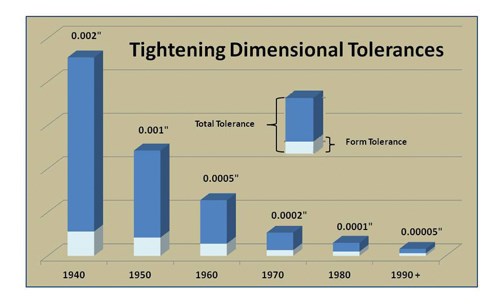
During the 1940s, demand for tighter-toleranced components increased due to war-related needs. Subsequent aeronautical requirements forced tolerances to become even tighter, putting demands on gaging that were unheard of at the time. Suddenly, manufacturers needed gaging that could perform solidly to 20 microinches. Until then, only super-sensitive dial indicators or dial comparators came close to this level of measuring performance. However, these devices were too fragile to be used in production environments and too slow to meet manufacturers’ high-throughput demands.
One solution was to set up precision calibration areas, or quality labs, where parts could be brought to those types of sensitive gages and measured. However, this approach took time, created bottlenecks and interrupted the manufacturing process.
Shopfloor Gaging
Taking highly capable measurement equipment out of central quality labs and setting it up to perform effectively near production processes was easier said than done. The quality labs eliminated vibration, unclean surroundings and temperature variation. Of these three precision-measurement enemies, temperature variation was the most serious roadblock for accurate dimensional gaging. That’s because materials change in size with changes in temperature, which is naturally problematic for measuring equipment that is located near machining processes. In spite of this, under the right conditions (such as when parts are small and comparative gaging with similar materials at similar temperatures are used), master and gage precision measurements could be made to the required levels of precision.
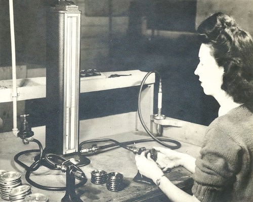
However, a new technology soon emerged to fill the need for high-precision measurements at the point of manufacture: air gaging. By applying the laws of the pressure/distance curve and using fixed plug gaging, air gaging became the first real game changer in shopfloor measurement.
Competing Tolerances
There is more to achieving tighter part tolerances than having the capability to perform complex measurements. Manufacturing processes were becoming harder to control. Because effective process control can only be accomplished with reliable data, obtaining the necessary data added to the challenge of taking measurements. This meant more capable measuring instruments were required.
This historic trend is likely to continue. High-precision components make up the bulk of U.S. manufacturing these days. So as dimensional tolerances become tighter, the relationships between dimensional tolerances, form tolerances and surface finishes become increasingly important. Unfortunately, they are oftentimes misunderstood or underestimated.
For example, many engineers do not realize that when specifying surface roughness with the average roughness parameter (Ra), the actual peaks of material present on the part’s surface are typically four to 10 times higher than the Ra value that’s measured or specified. This presents some real difficulties with dimensional and/or form tolerances on precision parts. The surface roughness characteristics are actually “using up” dimension or form tolerance and vice versa. Plus, a similar situation exists with form characteristics tending to “use up” a part’s dimensional tolerance. These factors must be taken into account when comparing the form tolerances to dimensional tolerances on the same part.
Process Control
Tighter tolerances became the norm for aero-nautic applications with the development of jet and rocket engines. High-performance bearings and components running at high rotational speeds and extreme temperatures forced gaging to become more precise and effective.
Manufacturers needed to make these high-quality parts quickly and easily while minimizing waste. That meant more manufacturing information was required, creating a need for a method to collect it. Such efforts started with pre-control and simple graphs of Deming’s statistical process control (SPC). However, logging data by hand was labor-intensive, subject to human error and a hindrance to operators’ primary task of making parts.
Electronics
As planes became faster and could travel farther, it became impossible for pilots to control every aspect of the flying. Therefore, electronics and computers were needed to help fly high-powered aircraft. However, unlike existing power-hungry electronics, aircraft electronics had to be small, use little power and have great computing capabilities. Once such electronics were created for the aeronautical industry, they started to be applied in manufacturing and quality control as well.
Many new electronics-based innovations suddenly became available in the gaging world. The first generation of precision electronics offered capabilities beyond those of air gaging. New bench amplifiers and electronic probes enabled manufacturers to take micro-inch and even sub-micro-inch measurements on the shop floor.
Still, manufacturers needed to more fully understand their processes. This required better data, meaning the newly implemented electronics needed the ability to share information and output data from the gaging process. New languages and communications tools seemed to appear overnight, including BCD, ASCII, RS-232 and parallel.
Microprocessors
The first microprocessors originally developed for aeronautical control and guidance systems started to become part of everyday life and were soon used with gaging. These microprocessors were slow, big, clunky and somewhat hard to use by today’s standards. However, they provided immediate measurement feedback at the point of manufacture. When the first automated form and surface-finish gages were introduced, they were immediately placed in manufacturers’ calibration areas. This helped speed the analysis of form and surface finish.
Microprocessors for data collection and analysis soon followed. The first dedicated statistical analyzers and multiple-input data-collection devices created an entirely new industry for data collection and analysis. Electronic data collection improved data quality. Prior to this, data was either handwritten and entered into a computer, or entered into the computer directly at the point of gaging. These bottlenecks were virtually eliminated by sending data directly to a data collection and analysis device. When electronic data collection processes were first implemented, it was not unusual to see collection efficiencies and error reduction improve tenfold over manual collection.In addition, the electronics industry kept developing technologies that were smaller, faster and required less power to operate. New devices were such power-sippers that they could run for a year or more with just a small, replaceable battery.
Digital Indicators
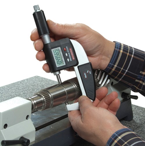
The metrology industry was next presented with the opportunity to use these new electronics to create portable, handheld digital gages capable of transmitting information. This made virtually every measuring station in a shop a data-gathering point. Dial indicators became digital indicators, vernier calipers became digital calipers and so on. Micrometers, weight scales and gages for measuring hardness, height, surface finish and coating thickness became digitized and had the ability to readily share data.
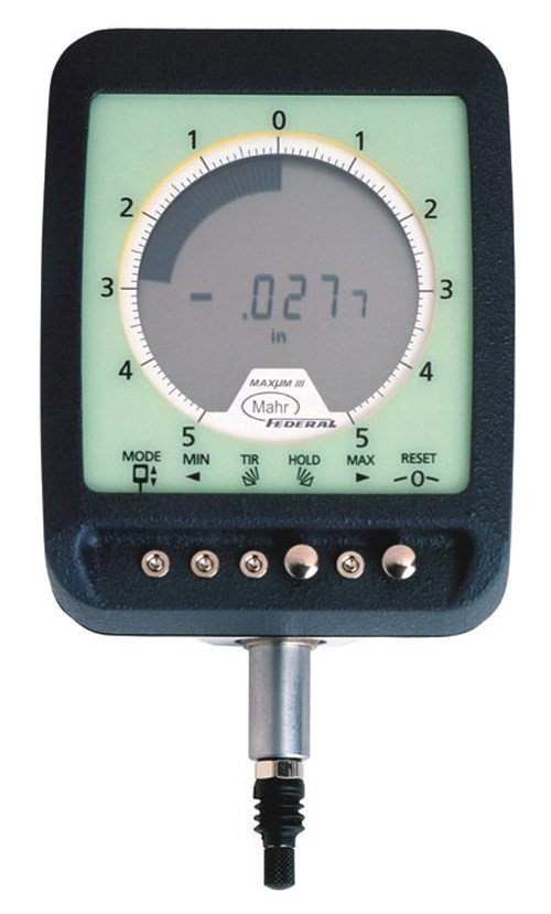
In addition, many of today’s digital indicators and hand tools are capable of matching the resolution and performance once reserved for bench amplifiers and other bench analytical tools. It is not uncommon to find features such as dynamic measurement, multiple factors, unilateral tolerances, different output formats and micro-inch resolutions in higher-end digital indicators. And while they may be high-end for digital indicators, they are still about a quarter of the price of a bench amplifier and probe.
The “fifth of a grad” has become just another digit on the indicator. Plus, many modern digital indicators have some form of supplemental analog display. These electronic emulations of analog functionality serve to eliminate some of the cognitive disadvantages of digital displays. They make digital indicators more user-friendly because they give the impression of direction and show where a part measurement falls within or exceeds the tolerance band.
These days, it’s normal to check parts at a gaging station with a hand tool or a dedicated fixture gage connected to a computer for data collection. Modern hand tools and digital indicators have data output built in, and collecting data is easy and very cost effective. It is also inexpensive, fast and reliable, and it provides a great solution for many process or quality-control applications.
Ease of Use
That said, bringing measuring instruments to the shop floor and near manufacturing process means taking them out of the hands of dedicated measurement technicians and putting them into the hands of machine operators. Those operators usually do not have the same level of metrology training as measurement technicians, and don’t have the time to spend on training. To accommodate this, many instrument manufacturers are striving to make sophisticated measurement instruments easier to use.
Some manufacturers have developed simple-to-use touchscreen interfaces for computerized systems. Touchscreen interfaces are generally less intimidating than the common Windows interface with a mouse. Using a touchscreen is more like pushing buttons on a machine than manipulating a computer. However, some of the latest products combine a Windows interface and a touchscreen interface, enabling the user to choose how to operate the instrument. Plus, user profiles can be created so that personal preferences are applied automatically upon log in.
Wi-Fi
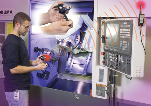
In some instances, a part can’t be brought to a gaging station because it is still in a machine or it is simply too large to easily transport. Running a long cable from the gage to the computer can be a hazard, and if multiple dimensions need to be checked with different gages, a collection of long cables can quickly become a snarled mess. The answer to this problem is to use wireless technology on the shop floor.
Small transmitters are now available for most gages, digital indicators and other hand tools enabling them to wirelessly transmit data hundreds of feet to the gaging computer. Each transmitter uses slightly different signal coding so many gaging stations can communicate to a single computer simultaneously. Of course, these transmitters can cost five to 10 times more than data cabling, but the cost is justified when cabling won’t get the job done.
In addition, many transmitters provide feedback by generating a signal to the operator that the transmission was received by the computer. This is virtually instantaneous so as not to slow down the operator, and most transmitters can be configured to provide a go/no-go signal to indicate whether or not the part is within tolerance.
In-Process Gaging
Perhaps the best use of wireless-transmission technology is to facilitate in-process gaging at a machine tool. By transmitting measurement data wirelessly to a machine’s CNC, the CNC can use the data to automatically calculate offsets, greatly improving machining quality and throughput. This minimizes the chance that the machine will make out-of-spec parts. In addition, the data can be archived and used for tracking purposes and to improve operator throughput because it is known when the part was measured and by whom.
Bringing it All Together
The combination of digital gaging for accurate shopfloor measurement, unrestricted wireless transmission of reliable data and statistics for process control makes for the most effective use of measurement data. This is important to address the widespread need for tighter tolerances in U.S. manufacturing that is pushing the limits of process control and forcing many companies to look for better data on which to base their processes. Factors such as the relationship of the form and surface roughness tolerances to dimensional tolerances must be taken into account. This wasn’t always as easy as it is today.
However, the technology that created the need for tighter tolerances also provided the means for making those measurements at the point of manufacture and provided a way to easily and reliably collect data. This cycle will continue. Although many gaging technologies have come and gone in only a matter of years, they have always been replaced by something that is faster, easier to use and usually more cost-efficient. It’s a pretty safe bet that the introduction of the new iPad is going to affect metrology somewhere in the near future as well.
About the author: George Schuetz is director-precision gages for Mahr Federal Inc.
Related Content
Process Control — Leveraging Machine Shop Connectivity in Real Time
Renishaw Central, the company’s new end-to-end process control software, offers a new methodology for producing families of parts through actionable data.
Read MoreThe Many Ways of Measuring Thickness
While it may seem to be a straightforward check, there are many approaches to measuring thickness that are determined by the requirements of the part.
Read MoreOrthopedic Event Discusses Manufacturing Strategies
At the seminar, representatives from multiple companies discussed strategies for making orthopedic devices accurately and efficiently.
Read MoreBallbar Testing Benefits Low-Volume Manufacturing
Thanks to ballbar testing with a Renishaw QC20-W, the Autodesk Technology Centers now have more confidence in their machine tools.
Read MoreRead Next
Building Out a Foundation for Student Machinists
Autodesk and Haas have teamed up to produce an introductory course for students that covers the basics of CAD, CAM and CNC while providing them with a portfolio part.
Read MoreRegistration Now Open for the Precision Machining Technology Show (PMTS) 2025
The precision machining industry’s premier event returns to Cleveland, OH, April 1-3.
Read More5 Rules of Thumb for Buying CNC Machine Tools
Use these tips to carefully plan your machine tool purchases and to avoid regretting your decision later.
Read More



.png;maxWidth=150)


.jpg;maxWidth=300;quality=90)


.jpg;maxWidth=300;quality=90)


