5 Tips for Selecting the Optimal Spindle Range
Learn how to select the appropriate spindle range and ensure that your CNC machining center or turning center is running an optimized cycle.
Share


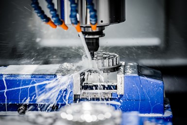
Optimal range can improve the productivity of the spindles on your metal cutting CNC machines.
Regardless of whether you are using a CNC milling machine in which the spindle rotates the cutting tool or a CNC lathe in which the spindle rotates the workpiece, larger CNC machines have multiple spindle ranges. The lower spindle range provides more power, and the higher range provides more speed. It is critically important to ensure that machining is done in the appropriate spindle speed range to achieve optimum productivity. Here are five tips for selecting the appropriate range:
1) Know your spindle’s power and speed characteristics.
Machine tool builders publish spindle characteristics in their operator manuals. There, you will find the lowest and highest rpm for each range, along with how much power to expect throughout the rpm range.
If you have never studied this important data, it is likely that your cycle times are not optimized. Worse, you may be placing undue stress on your machine’s spindle motor, or even stalling it. Digging out the manual and learning about spindle characteristics can help you optimize your machine’s productivity.
2) Know how long it takes to change spindle ranges.
There are at least two kinds of spindle-range changing systems: those with spindle drive motors that incorporate multiple windings and those with mechanical transmissions.
The former change ranges electronically by changing which motor windings they use. These changes are nearly instantaneous.
Systems with mechanical transmissions typically are direct drive at their highest range and engage the transmission with lower ranges. Range changing may take several seconds, especially if the spindle must stop during the process.
3) Know how to select spindle range.
With CNCs, spindle range changes are somewhat transparent because spindle speed is specified in rpm, the S-word that specifies speed also causes the machine to select the related spindle range. Say a machine’s low range runs from 20-1,500 rpm and the high range runs from 1,501-4,000 rpm. If you were to specify an S-word of S300, the machine would select the low range. An S-word of S2000 causes the machine to select the high range.
An ill-informed programmer can unwittingly cause two problems.
First, the program may be causing unnecessary range changes from tool to tool. With mechanical transmissions, this will increase cycle time but may go unnoticed since it only manifests when some tools take longer to change than others. Running tools requiring the same range in sequence will reduce cycle time.
Second, the spindle-speed rpm calculation for a powerful roughing operation may put the spindle at the low end of the high-spindle range, where there is limited power. This will place undue strain on the spindle drive system or cause the spindle motor to stall. A well-informed programmer will compromise spindle speed slightly downward, selecting the highest speed in the low range, where there is ample power to perform the machining operation.
With turning centers, spindle range changing is done with M-codes, and higher ranges usually overlap lower ranges. For a turning center with three spindle ranges, the low range may correspond to M41 and run from 30-1,400 rpm, the middle range may correspond to M42 and run from 40-2,800 rpm, and the high range may correspond to M43 and run from 45-4,500 rpm.
4) Know how spindle speed can affect cycle time.
This point applies only to turning centers and operations that utilize constant surface speed. With constant surface speed, the CNC will constantly select speed in rpm based on a speed specified in surface feet or meters per minute and the diameter currently being machined.
Spindle speed is inversely proportional to time when you set the feed rate in a per-revolution fashion. If you can double spindle speed, the time required for the related machining operation will be cut in half.
A popular rule of thumb for spindle range selection is to rough machine in the low range and finish machine in the high range. While this is good rule of thumb for ensuring the spindle has adequate power, it does less well at considering speed.
Consider a 1-inch-diameter workpiece that must be rough- and finish-turned. The recommended speed is 500 sfm for the roughing tool. Even at the largest diameter (1 inch), this renders 1,910 rpm (3.82 times 500 divided by 1). Smaller diameters will require even higher rpms. If the programmer selects the low range based on the rule of thumb, the spindle will hit a 1,400-rpm limit. The roughing operation will finish faster in a higher range, assuming there is adequate power.
5) Know when to change spindle ranges.
This point also applies only to turning centers and roughing operations requiring constant surface speed. Consider rough-turning a 4-inch-diameter shaft that has several diameters, the smallest of which is 1 inch. Say the recommended speed is 800 sfm. At 4 inches, the required speed is 764 rpm. The low range will provide the needed power.
As rough-turning continues, diameters get smaller and rpm increases. At 2.125 inches, optimal machining requires over 1,400 rpm, but the spindle will peak out in the low range at 1,400 rpm, and each successive roughing pass will take longer than it should. It would be wiser to switch to the middle range at this point, especially if range changing is instantaneous.
Related Content
5 Tips for Running a Profitable Aerospace Shop
Aerospace machining is a demanding and competitive sector of manufacturing, but this shop demonstrates five ways to find aerospace success.
Read MoreHow to Mitigate Chatter to Boost Machining Rates
There are usually better solutions to chatter than just reducing the feed rate. Through vibration analysis, the chatter problem can be solved, enabling much higher metal removal rates, better quality and longer tool life.
Read MoreGenerating a Digital Twin in the CNC
New control technology captures critical data about a machining process and uses it to create a 3D graphical representation of the finished workpiece. This new type of digital twin helps relate machining results to machine performance, leading to better decisions on the shop floor.
Read MoreERP Provides Smooth Pathway to Data Security
With the CMMC data security standards looming, machine shops serving the defense industry can turn to ERP to keep business moving.
Read MoreRead Next
Setting Up the Building Blocks for a Digital Factory
Woodward Inc. spent over a year developing an API to connect machines to its digital factory. Caron Engineering’s MiConnect has cut most of this process while also granting the shop greater access to machine information.
Read MoreRegistration Now Open for the Precision Machining Technology Show (PMTS) 2025
The precision machining industry’s premier event returns to Cleveland, OH, April 1-3.
Read MoreBuilding Out a Foundation for Student Machinists
Autodesk and Haas have teamed up to produce an introductory course for students that covers the basics of CAD, CAM and CNC while providing them with a portfolio part.
Read More
.jpg;width=70;height=70;mode=crop)


.jpg;maxWidth=300;quality=90)


