4 Things to Incorporate in CAM-System-Generated CNC Programs
Streamline G-code programs created by CAM systems.
Share


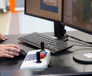
Using a CAM system is the most popular method of creating CNC programs.
There are three ways to create programs that run on CNC machines: manually write them, use a shopfloor-programmed conversational control or use a CAM system. The last is the most popular method of creating programs because almost every company that has CNC machine tools has a CAM system.
Just as a CNC control can be customized through parameter settings to work with a wide variety of CNC machine tools, so too can a CAM system be tailored to work with a wide variety of CNC controls. However, given the numerous CNC functions involved, customizing the CAM system to a given CNC machine and control can be challenging.
To complicate matters, most CNCs allow users to handle nearly every programming feature multiple ways based on preference. With cutter radius compensation, for instance, the user can decide whether the generated tool path is for the cutter centerline or the work surface. Choices are often based on legacy because CNCs are “backward compatible.” This means they allow older programming methods to be used for years (or decades) after newer, more convenient features became available.
Given the these complexities, most companies tend to quit customizing CAM system G-code output as soon as they get something that works. They stop short of making the CAM system output G-code programs that are properly structured, or that takes advantage of current, more desirable CNC features. Resulting G-code programs are lengthier, less efficient and more cumbersome than their manually created counterparts.
How do you streamline G-code programs created by CAM systems?
Here are four suggestions to help you streamline G-code programs created by CAM systems.
1. Simplify operator involvement.
Certain CNC features are designed to make life easier for manual programmers. The tradeoff is often more work for setup people and operators. Consider tool nose radius compensation, a turning center feature that deals with imperfections caused by the tiny radius on single-point cutting tools. While it simplifies programming, CNC-based tool nose radius compensation requires the setup person to enter tool nose radius data.
All current CAM systems can output tool paths based on a specified tool nose radius. If you make your CAM system do so, you can save setup time and minimize potential for mistakes. Other CNC features that can have an impact on operator time and effort include other compensation functions like machining center based fixture offsets, tool length compensation and cutter radius compensation, as well as turning center based geometry and wear offsets.
2. Make programs easier to interpret and modify.
While they may not regularly modify CNC programs, setup people and operators should be able to understand what a G-code program is doing. This can be a direct function of how your CAM system generates G-code programs. Your CAM system should take advantage of CNC features like decimal point programming (I still see CNC words including real numbers generated with fixed format), radius designation for circular commands using R instead of I, J and K, and canned cycles instead of multiple G00/G01 motion commands. It should also utilize coordinate manipulation features when applicable, like coordinate rotation, single direction positioning, mirror image and scaling.
3. Clean up program structure.
CAM systems are notorious for generating G-code programs with redundancy. Unnecessary, redundant commands in a program increase program length and can confuse operators. A CAM system may, for example, include the motion type G00, G01, G02 or G03 in every motion command even though motion type is modal.
Conversely, I’ve seen resulting G-code programs that do not allow the rerunning of cutting tools — a task commonly required when running the first workpiece in a production run — or when critical finishing tools are replaced after wearing out. Rerunning a tool requires that all commands needed to get the program running be included at the beginning of every tool.
4. Deal with the results of probing using custom macro.
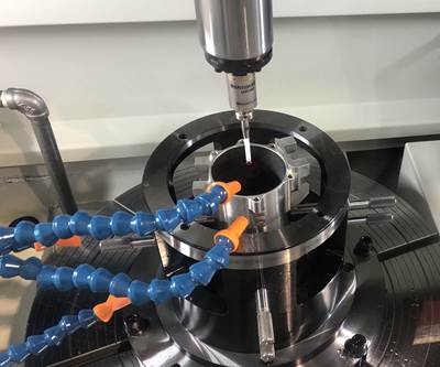
Spindle probes have become very popular and are especially helpful during setup, but they are also becoming an integral part of many CNC cycles as well. They are commonly used to automate trial machining operations, ensuring the correctness of a surface machined for the first time with a new cutting tool. They can also be used when raw material to be machined varies from part to part, which is commonly the case with castings and forgings. With these kinds of applications, the CAM-system-generated CNC program must dynamically deal with probing results in real time.
For example, stock on a workpiece surface may be varying from 0.05 inch to 0.25 inch. Rather than waste time by making the number of passes for the worst-case scenario, the spindle probe can determine the amount of material that must currently be machined. If it determines that there is 0.2 inch of material on a surface to be milled, the CNC program must make the appropriate number of machining passes.
Since the number of passes will vary from part to part, many of the resulting machining commands cannot be performed directly by the CAM-system-generated G-code program. Instead, the CAM system must have the G-code program call a parametric program (custom macro in FANUC terms) that resides in the CNC control and makes the correct number of passes based on the results of the probing operation.
Related Content
How this Job Shop Grew Capacity Without Expanding Footprint
This shop relies on digital solutions to grow their manufacturing business. With this approach, W.A. Pfeiffer has achieved seamless end-to-end connectivity, shorter lead times and increased throughput.
Read MoreCan ChatGPT Create Usable G-Code Programs?
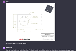
Since its debut in late 2022, ChatGPT has been used in many situations, from writing stories to writing code, including G-code. But is it useful to shops? We asked a CAM expert for his thoughts.
Read MoreGenerating a Digital Twin in the CNC
New control technology captures critical data about a machining process and uses it to create a 3D graphical representation of the finished workpiece. This new type of digital twin helps relate machining results to machine performance, leading to better decisions on the shop floor.
Read MoreTips for Designing CNC Programs That Help Operators
The way a G-code program is formatted directly affects the productivity of the CNC people who use them. Design CNC programs that make CNC setup people and operators’ jobs easier.
Read MoreRead Next
CNC Tech Talk: 2 Lesser-Known Ways to Trigger the Skip Signal
Here are two lesser-known ways to trigger the skip signal.
Read MoreHow to Effectively Train CNC Machine Operators
A blended-learning approach uses external resources to teach the basics, saving in-house training for company-specific issues.
Read More5 Mistakes We Find in Most CNC Machine Programs
While the mistakes listed here will not sound an alarm or cause a program to fail, they will cause confusion, wasted time and scrap parts.
Read More
.jpg;width=70;height=70;mode=crop)


.jpg;maxWidth=300;quality=90)


