Things You Should Know About Digital Height Gages
With its long range of motion, the digital height gage can be thought of as a giant caliper, but one with the accuracy of a sophisticated benchtop gaging system. These versatile digital height gages are capable of performing a range of measuring tasks quickly and reliably.
Share


Hwacheon Machinery America, Inc.
Featured Content
View More


With its long range of motion, the digital height gage can be thought of as a giant caliper, but one with the accuracy of a sophisticated benchtop gaging system. These versatile digital height gages are capable of performing a range of measuring tasks quickly and reliably.
Digital height gages consist of the base plate, the height measuring station and the control/evaluation display. The measuring station is suited for one-dimensional coordinate measurements in a vertical direction. It is therefore used primarily for determining diameters and the distances between points on the test piece. Two-dimensional measurements are possible, however, if the test piece can be tilted 90 degrees and the control/evaluation display has the capability of calculating the 90-degree coordinates.
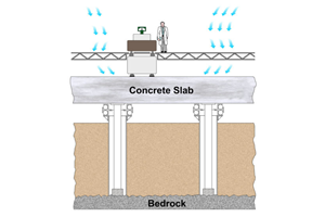
The height gage measuring area is bordered by the base plate and the stylus. Some gages are capable of measuring 40 inches or more, but most fall into the 24-inch range, and they are most often used in the lower 12 inches of that range. Because the base of the height gage is part of the measuring circuit, the base on which it rests is important. Height gages should be used on a grade 0 or grade 1 granite base plate. The granite plate should be mounted on a vibration-insulated stand to eliminate vibrations.
The quality of a measuring result depends on the quality of the measuring instrument and the care with which the operator handles the measurement procedure. Here’s how the operator can contribute to the quality of the measuring results.
On a day-to-day basis, the gage should be given the “once-over” prior to use:
- Wipe off the table and the contact probe; clean up the area around the gage.
- Turn on the gage and let it set its reference location.
- Let it sit for a minute; then re-zero it again to check repeat.
- Although the probe diameter is stored in the memory of most height gages, it does not hurt to re-master the probe diameter occasionally.
Good height gage practice includes the following operational standards:
- Keep the plate free from dust, chips and dirt.
- Do not use the height measuring instrument for marking.
- The body heat of the operator 98.6°F (37°C) is clearly above the room temperature 68°F (20°C). Any heat conveyed to elements of the measuring circuit (the base plate, the test piece, the height measuring instrument, stylus) causes local heat expansion and thus measurement error.
- Re-zero on a regular basis.
- As noted, height gages are most often used in the lower 12 inches of the range. With any length measuring system, the accuracy degrades the further you move from the reference point. When measuring on the upper end of the scale, performance can be improved by zeroing on a 12-inch gage block, or something closer to the midpoint of the operating range for the particular test piece.
You should also observe the following rules:
- Use gloves to avoid touching the test piece directly with your bare hands before the measurement. Do not touch other elements of the measuring circuit.
- Only touch the height measuring instrument at the points provided for this purpose.
- Avoid placing the gage in drafts or direct sunlight.
- Do not set up the measuring station in the proximity of radiators.
- Do not check test pieces that were recently transported through very hot or cold rooms.
- For high-precision measurements place the test piece on the base plate and let it adapt to ambient temperature.
- Generally, use the air bearings only for positioning the height measuring instrument before a measurement.
- Gages with motor drives tend to improve performance by using a constant gaging force as the test piece is measured.
- Adjust the gage settling time to best match the application. During this time, the measuring values “oscillate” accordingly. Thus, the instrument has to wait until the measuring value is stable before it acquires the value.
- Long contact points are apt to flex when they contact the part. It may be necessary to build contacts with “bridge” reinforcements if deflection is noticed.
By gaining experience and following these steps, the inspector can make this giant caliper his or her best friend when measuring a variety of parts.
Related Content
How to Calibrate Gages and Certify Calibration Programs
Tips for establishing and maintaining a regular gage calibration program.
Read MoreCustom Workholding Principles to Live By
Workholding solutions can take on infinite forms and all would be correct to some degree. Follow these tips to help optimize custom workholding solutions.
Read More4 Steps to a Cobot Culture: How Thyssenkrupp Bilstein Has Answered Staffing Shortages With Economical Automation
Safe, economical automation using collaborative robots can transform a manufacturing facility and overcome staffing shortfalls, but it takes additional investment and a systemized approach to automation in order to realize this change.
Read More4 Commonly Misapplied CNC Features
Misapplication of these important CNC features will result in wasted time, wasted or duplicated effort and/or wasted material.
Read MoreRead Next
Building Out a Foundation for Student Machinists
Autodesk and Haas have teamed up to produce an introductory course for students that covers the basics of CAD, CAM and CNC while providing them with a portfolio part.
Read More5 Rules of Thumb for Buying CNC Machine Tools
Use these tips to carefully plan your machine tool purchases and to avoid regretting your decision later.
Read MoreRegistration Now Open for the Precision Machining Technology Show (PMTS) 2025
The precision machining industry’s premier event returns to Cleveland, OH, April 1-3.
Read More


.png;maxWidth=150)


.jpg;maxWidth=300;quality=90)


