Structuring a Part Family Custom Macro
There are three common ways to get data into the program.
Share


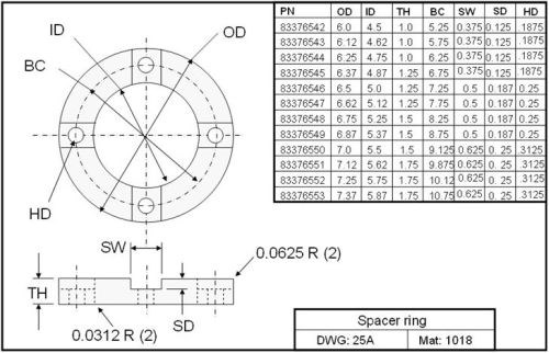
Good part family applications are pretty easy to spot. There is, of course, a high degree of similarity among the parts in the family. The same processes (and cutting tools) are commonly able to machine all workpieces in the family, and one drawing may be used to describe several workpieces. Variables on the drawing are used in place of dimensions, and a chart shows the variable values for each workpiece being described. The drawing at left shows a simple example.
The first challenge that faces a part family programmer is how to get data into the custom macro program. There are three common ways to accomplish this. First, a series of common variables can be included at the beginning of the program to specify the input data:
O0001 (Main program)
#101 = 4.5 (Inside diameter)
#102 = 6.0 (Outside diameter)
#103 = 5.25 (Bolt circle diameter)
#104 = 1.0 (Thickness)
#105 = 0.125 (Slot depth)
#106 = 0.375 (Hole diameter)
(Machining program begins here)
M30 (End of program)
With this method, the input data is included as part of the custom macro program(s), and the setup person will modify this data as he or she goes from one part in the family to another.
Most companies, however, do not want the setup person involved in this process. They would rather have the input data included in a separate program that can be saved and retrieved using a distributive numerical control (DNC) system.
O0001 (Main program)
M98 P1000 (Call part definition program)
(Machining begins here)
M30 (End of program)
Now the series of common variables (in program O1000) is separated from the custom macro program(s) and can be stored separately.
A third way to get data into a part family custom macro is helpful with more complex applications when there is a lot of input data requiring many variables. With this method, a programmer will pick and choose required data as it is needed.
O1000 (Part definition program)
GOTO #19
N1#100 = 83376542 (Part number)
GOTO 99
N2 #100 = 4.5 (Inside diameter)
GOTO 99
N3#100 = 6.0 (Outside diameter)
GOTO 99
N4#100 = 5.25 (Bolt circle diameter)
GOTO 99
N5#100 = 1.0 (Thickness)
GOTO 99
N6#100 = 0.125 (Slot depth)
GOTO 99
N7#100 = 0.375 (Hole diameter – vacant if no
drilling is done)
GOTO 99
N8#100 = 0.0625 (OD radius – vacant
if chamfer)
GOTO 99
N9#100 = #0 (OD chamfer – vacant
if radius)
GOTO 99
(More variables here)
N99 #[#22] = #100 (Set variable value)
M99 (End of part definition program)
Notice that each variable is related to a sequence number (N word). N5, for instance, is related to the workpiece thickness. Also notice that we temporarily use common variable #100 to store each piece of data. At the end of the program (in N99), the value of #100 is transferred to a variable of our choosing, which is specified in the command that gets data. If, for example we currently need the inside diameter, outside diameter and bolt circle diameter, these three commands will retrieve them and store them in common variables #101, #102, and #103, respectively.
G65 P1000 S2.0 V101.0 (Inside diameter)
G65 P1000 S3.0 V102.0 (Outside diameter)
G65 P1000 S4.0 V103.0 (Bolt circle diameter)
Getting all the data for part family applications into a custom macro program might seem like a challenge for the programmer, but these three methods should simplify that process.
Related Content
3 Mistakes That Cause CNC Programs to Fail
Despite enhancements to manufacturing technology, there are still issues today that can cause programs to fail. These failures can cause lost time, scrapped parts, damaged machines and even injured operators.
Read MoreHelp Operators Understand Sizing Adjustments
Even when CNCs are equipped with automatic post-process gaging systems, there are always a few important adjustments that must be done manually. Don’t take operators understanding these adjustments for granted.
Read More4 Commonly Misapplied CNC Features
Misapplication of these important CNC features will result in wasted time, wasted or duplicated effort and/or wasted material.
Read More4 Reasons to Use Safety Commands
Safety commands help safeguard CNC applications from common programming or operation errors.
Read MoreRead Next
Registration Now Open for the Precision Machining Technology Show (PMTS) 2025
The precision machining industry’s premier event returns to Cleveland, OH, April 1-3.
Read More5 Rules of Thumb for Buying CNC Machine Tools
Use these tips to carefully plan your machine tool purchases and to avoid regretting your decision later.
Read MoreSetting Up the Building Blocks for a Digital Factory
Woodward Inc. spent over a year developing an API to connect machines to its digital factory. Caron Engineering’s MiConnect has cut most of this process while also granting the shop greater access to machine information.
Read More
.jpg;width=70;height=70;mode=crop)


.png;maxWidth=300;quality=90)


