Precision cleaning solvents
Published

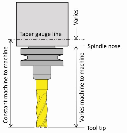
Refining Tool Length Compensation Usage

Some methods enable offset values to be determined offline.

Share

For years, I have taught two ways to utilize tool length compensation. My preferred method is to use the length of the cutting tool as the tool length compensation offset value. With this method, the program zero assignment value in Z (the workpiece coordinate system offset Z value) is the distance from the face of the spindle at the Z-axis zero return position to the program zero surface in Z. I prefer this method, because tool length compensation offset values can be determined offline.
 
With the second method, the tool length compensation value is the distance from the tooltip while the Z axis is at the zero return position to the program-zero surface in Z, and the program-zero assignment value in the Z axis is zero.
 
Now, I’d like to suggest a third method for tool length compensation usage, which is actually an off-shoot of my preferred method. It was suggested to me by Tim Fenner, computerized manufacturing and robotics programs manager at BIR Training Center in Chicago.
 
I have always defined tool length for tools held in tapered holders (such as CAT and BT-style toolholders) as the distance from the tooltip to the spindle nose. This works nicely if you don’t share cutting tools among machines or if you don’t use an offline tool length measuring device to measure tool lengths for multiple machines. But if you do, you must consider that the tapers within spindles vary slightly from machine to machine, and this variance causes a deviation for tools measured for one machine and then used in another.
 
You can compensate for this deviation with a common work coordinate system offset (offset number zero). Simply pick a machine as the standard, and enter the variation in the common work coordinate system offset Z register for the others—a different value for each machine. With this method, the same tool length compensation value for a given tool can be used in any machine. However, this eliminates—or at least complicates—the use of the common fixture offset for other purposes, like shifting the point of reference for workpiece coordinate system offset entries.
 
Toolholder and tool length measuring device manufacturers specify a gage line that is consistent among tapered toolholders and spindles, as shown in the illustration here. While the distance from the gage line to the spindle nose changes from machine to machine, the distance from the gage line to the tooltip will not vary.
 
Therefore, with this third method, I define the tool length—the value going into the tool length compensation offset register—as the distance from the tooltip to the gage line. Since this value is consistent among machines, cutting tools can be measured offline and shared among machines without having to use the common workpiece coordinate system offset.
 
If you adopt this method, there are two important tool length compensation functions to consider: the Z-axis program zero assignment value and, if lengths are sometimes measured on the machine, how setup people and operators measure them.
 
The Z-axis program zero assignment value will now be the distance from the gage line to the Z-axis program zero point. One way to measure this is to use a tool (or aligning bar) whose length has been properly measured using a tool length measuring device. Say the length (the distance from the tooltip to the gage line) is 5.2736 inches. With the tool in the spindle, bring its tip to the Z-axis program zero surface. From the value of the Z-axis machine position display register (the distance from the Z-axis zero return position to the gage line—a negative value), subtract the length of the cutting tool or aligning bar—5.2736 inches in our case. The result is the Z-axis program zero assignment value.
 
You can probably come up with several ways to measure the tool length compensation value on the machine, but if you adopt this new method, you won’t want to do so very often. If you do, it might be better to stick with your previous methods.
 
One way to measure tool lengths on the machine is to determine, one time, the distance from the spindle nose to the gage line. Say you find it to be 0.4773 inch. Manually bring the spindle nose to a flat surface (like the 3-inch side of a one-two-three block). With the spindle nose touching the block, preset the Z-axis display to 0.4773. Now back off, load a tool, and bring the tooltip down to the same block. The Z axis display will show the tool’s tool length compensation value.
Precision Cleaning Solvents
Cleaning Technologies Group
Echoflex modular ultrasonic cleaning machines
Parts Cleaning Conference
high-performance systems for efficient parts cleaning
EZ Access - Have it all with Ez - Mazak
IMTS 2024
Hurco
BIMU 2024
Universal Homepage Package W4900 Indicator
Koma Precision
JTEKT

Read Next

Basics

Obscure CNC Features That Can Help (or Hurt) You

You cannot begin to take advantage of an available feature if you do not know it exists. Conversely, you will not know how to avoid CNC features that may be detrimental to your process.

Read More
Turning Machines

A History of Precision: The Invention and Evolution of Swiss-Style Machining

In the late 1800s, a new technology — Swiss-type machines — emerged to serve Switzerland’s growing watchmaking industry. Today, Swiss-machined parts are ubiquitous, and there’s a good reason for that: No other machining technology can produce tiny, complex components more efficiently or at higher quality.

Read More

Encountering Surface Finishes in the Everyday World

Surface measurement is becoming increasingly important to ensure proper performance of a manufactured product. Advanced surface measurement tools are not only beneficial in the manufacturing industry but also have unconventional applications.

Read More
Precision cleaning solvents