
Height Gages from the Top
Today’s instruments can produce other useful measurements as well.


George Schuetz
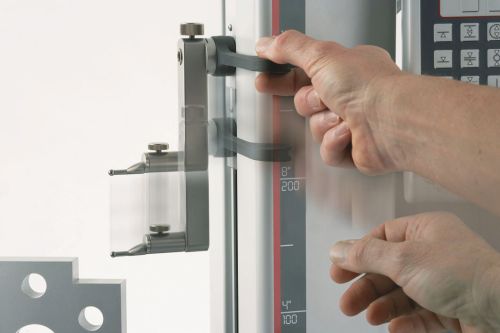
Some height gages incorporate a quick-adjusting release that enables the measuring point to be moved directly to the location of the check before the measuring system takes over.
Share


.png;maxWidth=45;format=webp)
DMG MORI - Cincinnati
Featured Content
View More


ECi Software Solutions, Inc.
Featured Content
View More


Autodesk, Inc.
Featured Content
View More
Takumi USA
Featured Content
View MoreThe height gage is a conceptual extension of the handheld caliper gage, except that it rests on a heavy base that keeps the scale square to the surface. Originally, height gages were designed with a beveled pointer on the moveable jaw that was used either to mark or scribe the part during layout work, or to find a height characteristic on a part and display it on the gage’s readout.
Today, height gages are not only designed to do what their name implies—measure height—but also to measure diameters, distances and even bolt circle patterns. So instead of a beveled pointer, a family of interchangeable contact points is available with a vast array of diameters, shapes, and even offsets, to get into virtually any characteristic on a part.
Measurement Setup
Once you have the height gage set in place, there are two critical references that need to be established. The first is the zero reference for the measuring system. With automated height gages, this occurs when the gage is turned on and automatically moves to touch the surface to set its reference point. Recommended practice is to then initiate this zeroing routine a second time, just to make sure that no dirt or other anomaly has introduced an incorrect reference.
The other important reference that must be established is the correction for probe ball diameter. If a height gage is to be used only for length measurements taken with the probe moving down, then probe diameter is not important. The contact point of the probe will be the same as in zeroing. But, if grooves, diameters or hole locations are being measured, or if any measurements are taken with the probe moving upwards, then the probe ball diameter must be determined and taken into account.
On height gages that have even the most basic electronic control, probe diameter can be measured as part of a setup routine and is automatically included in all measurements. The automated process uses a fixture provided with the gage that sets up a plane that is measured by the gage from both directions. The gage then looks at the difference between the two measurements and calculates this as the ball diameter.
Failing to recheck for ball diameter when a probe tip is changed can be a deadly pitfall. Going from a 10-mm to a 5-mm ball tip would be disastrous if not recalculated.
Making a Measurement
With new motorized digital versions, measurement is an easy keystroke function. When you are ready to make a measurement, say a height in reference to the zero point, slide the measuring carriage up over the part and press the height measurement button, approaching from the top. The motorized drive will bring the contact to the surface, and the measurement will be completed and displayed.
However, this only begins to describe the measuring capabilities of the modern height gage. Measurements are stored as they are made, and from this data, heights, midpoints, diameters and relationships are only a keystroke away.
Sources of Error
Regardless of type, all height gages have a similar inherent problem—they measure height—and the larger the height gage, the bigger the potential problem. It’s not the actual height that’s the problem; it’s the relationship between the height to the base.
A major error in designing a basic height gage is taking a design that was meant to measure 12 inches and simply extending the post to measure 36 inches, without changing the base design or the cross-area of the measuring post. The gage then will tend to wobble and flex. Although you may not be able to see the 0.001-inch wobble, it can become a significant part of the part tolerance and certainly influence the measurement.
Beefing up the column to reduce the flexure of the post offers only a partial improvement, as such a gage may still be top-heavy. What’s needed is to make the base longer and wider, and build in some mass. Decreasing the ratio of the post to the base will significantly improve performance.
Since the height gage is used with a surface plate, it can only be as good as that plate, which provides the reference for the part and the gage. Many surface plates are clean and well-maintained, but others may not be as clean as they look. A small imperfection, metal chip or even a hair, while almost impossible to see, could throw off the measurement by 0.020 inch at a height of only 10 inches.


Read Next

Building Out a Foundation for Student Machinists
Autodesk and Haas have teamed up to produce an introductory course for students that covers the basics of CAD, CAM and CNC while providing them with a portfolio part.
Read More
5 Rules of Thumb for Buying CNC Machine Tools
Use these tips to carefully plan your machine tool purchases and to avoid regretting your decision later.
Read More
Registration Now Open for the Precision Machining Technology Show (PMTS) 2025
The precision machining industry’s premier event returns to Cleveland, OH, April 1-3.
Read More