Zero Taper In Abrasive Waterjet Cutting
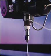
Abrasive waterjet machines use a high-velocity beam of water and abrasive particles to cut thick materials. This "floppy tool" has a tendency to cause tapered edges during cutting. Omax's IntelliMax software and Tilt-A-Jet technology is capable of producing zero taper without adversely affecting machining speeds. IntelliMax controls the cutting paths to ensure that the machine is operating at the highest possible speeds at all times. The Tilt-A-Jet can position the nozzle at the angle calculated by the software to offset the natural taper from the waterjet. The tapering effect is moved to the scrap side of the parent material, thus leaving square edges (zero taper) on the part.
Share


Abrasive waterjet machines offer a relatively simple way to precisely cut thick materials without generating heat that would otherwise warp or harden the material with other methods. The “cutting tool” used to penetrate materials such as Inconel, aluminum, stainless steel, titanium, composites and hardened tool steels is a high-velocity beam of water and abrasive particles. This “floppy tool” has a tendency to cause tapered edges during cutting.
Even a slightly pronounced taper can translate to quality issues, explains Dr. Axel Henning, manager of the R&D engineering department at Omax Corporation.
“The natural taper that a typical abrasive waterjet creates may not be large,” he says. “Nonetheless, it can still be problematic for a high-precision job.”
Offsetting this taper to meet tolerance requirements might entail sacrificing machining speeds. “To create perpendicular edges, the machine would normally have to slow down when approaching a corner to ensure that precision would not be compromised,” Dr. Henning explains.
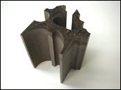
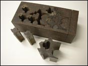
Howard Van Dyke, project engineer at Tool Technologies by Van Dyke, LLC, in Milford Center, Ohio, knows this scenario quite well. His shop purchased an Omax 55100 JetMachining center about 2 years ago. Its IntelliMax software and Tilt-A-Jet technology is capable of producing zero taper without adversely affecting machining speeds. Tool Technologies handles a substantial amount of prototype work as well as assembly jigs and checking fixtures for its automotive customers. These jigs and fixtures need to be made quickly and exactly to spec. Since the implementation of this technology, the company has held accuracies that range from ±0.001 to ±0.003 inch (±0.025 to ±0.076 mm) on the parts that it machines on a daily basis. Applications include cutting stacks of thin sheets and plates averaging 1 inch in thickness. The shop has occasionally cut plate as thick as 4 inches on the JetMachining center.
The machine’s control software automatically calculates the correct angle at which to tilt the machine’s cutting head to compensate for what Mr. Van Dyke refers to as “jet lag” during cutting. “When abrasive waterjet machining takes place, the water stream deflects in the opposite direction of the cutting path,” he explains.
“The software does the brunt of the work to compensate for this,” Dr. Henning says. “IntelliMax controls the cutting paths to ensure that the machine is operating at the highest possible speeds at all times.” The Tilt-A-Jet can position the nozzle at the angle calculated by the software to offset the natural taper from the waterjet. The tapering effect is moved to the scrap side of the parent material, thus leaving square edges (zero taper) on the part.
In fact, zero taper can be attained relatively easily with the machine’s PC-based interface. To activate the tilting feature on the machine, the operator need only make some basic decisions. Once the CAD file has been imported, the user enters the desired surface finish; defines the material type and thickness; and selects an optional box for the system to automatically calculate the tilt angle.
Another potential benefit of using the proactive software in concert with the custom nozzle is reduced cutting time. Dr. Henning estimates that users can expect reductions of about 20 to 30 percent because the machine has close control of the cutting path and can therefore operate at more consistent speeds, even when approaching corners.—MDA
Related Content
Where Micro-Laser Machining Is the Focus
A company that was once a consulting firm has become a successful micro-laser machine shop producing complex parts and features that most traditional CNC shops cannot machine.
Read MoreLean Approach to Automated Machine Tending Delivers Quicker Paths to Success
Almost any shop can automate at least some of its production, even in low-volume, high-mix applications. The key to getting started is finding the simplest solutions that fit your requirements. It helps to work with an automation partner that understands your needs.
Read MoreCNC Machine Shop Honored for Automation, Machine Monitoring
From cobots to machine monitoring, this Top Shop honoree shows that machining technology is about more than the machine tool.
Read MoreInside the Premium Machine Shop Making Fasteners
AMPG can’t help but take risks — its management doesn’t know how to run machines. But these risks have enabled it to become a runaway success in its market.
Read MoreRead Next
Setting Up the Building Blocks for a Digital Factory
Woodward Inc. spent over a year developing an API to connect machines to its digital factory. Caron Engineering’s MiConnect has cut most of this process while also granting the shop greater access to machine information.
Read MoreRegistration Now Open for the Precision Machining Technology Show (PMTS) 2025
The precision machining industry’s premier event returns to Cleveland, OH, April 1-3.
Read MoreBuilding Out a Foundation for Student Machinists
Autodesk and Haas have teamed up to produce an introductory course for students that covers the basics of CAD, CAM and CNC while providing them with a portfolio part.
Read More

