Vertical Machining Cells Challenge Horizontal Dominance
When part volumes are high, and success is measured in pennies and seconds, moving away from horizontal machines requires creative thinking about robotics, cutting tools, workholding and more.
Share


Hwacheon Machinery America, Inc.
Featured Content
View More

Takumi USA
Featured Content
View More


As far as Jordan Klint is concerned, Vickers Engineering is just the right size.
It’s certainly not too small. Decorated by the previous owner to resemble a castle, complete with mock parapets and a drawbridge, the facility immediately stands out. Still, first-time visitors might never guess that lurking behind this medieval façade is a cavernous 120,000 square feet of manufacturing space, where more than 100 CNC machining centers churn out engine, braking and other components for, as Mr. Klint puts it, “pretty much anything on wheels.” This kind of capacity makes the heavily automated, 170-employee company an important link in automotive supply chains (it enjoys Tier-One status for most work). It is also a critical partner for a slew of construction, agricultural, defense, and oil and gas industry clients. It is certainly an important fixture in New Troy, an unincorporated community of about 500 people in picturesque southwestern Michigan.
Yet, the company isn’t too large, either, Mr. Klint says, or at least it doesn’t feel that way. Since starting here in 2011 and climbing the ranks to engineering manager, he says he’s been given plenty of leeway in how he does his job. That’s thanks largely to the sort of culture one might expect to find at a much smaller company. Here, people are free to make their own way rather than being forced into rigid, pre-defined roles. “We’ve got the resources to invest when we need to, but we’re still small enough to be flexible and try new things,” he says.
Many new ideas originate with a special team of engineers and programmers that acts essentially as an in-house automation systems integrator. With both the desire and the authority to challenge accepted wisdom in search of a better way, this team exemplifies the company’s position between small, resource-strapped shops working with outside consultants and larger operations that lack the independence required for flexibility. Most recently, the team’s work has led Vickers Engineering to bet its future on the notion that, if configured properly, robot-fed vertical machining centers can be just as productive as robot-fed horizontals.
The key phrase, of course, is “if configured properly.” There are good reasons why the company has long standardized on horizontal machining centers (HMCs) over their less-expensive vertical cousins. High part volumes—some longstanding contracts exceed 1 million per year—leave little room for error, and initial machine cost savings would be for naught without keeping per-part costs and cycle times on par with what a horizontal could achieve. Making a new way has meant thinking differently about virtually every element of the process, from robot grippers and programming to cutting tools and workholding. “We live in a world of seconds and cents, and every one counts,” says Jeff Vickers, vice president.
Horizontal Roots, Vertical Growth
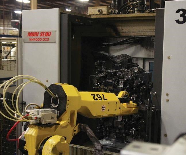
Since the company’s founding in 1970, the vast majority of high-volume parts have been machined from cast iron and aluminum castings on Mori Seiki NH4000 DCG and larger NH5000 DCG HMCs. One reason for standardizing on a horizontal machine configuration is that the spindle can access not just the front faces of the workpieces, but also the ends/sides of those on the left and right faces of the tombstone, all in the same setup. In the meantime, loading/unloading can proceed on the second pallet, a task that’s largely been automated since the installation of the company’s first robot arm in 2006.
Although verticals can be fitted with pallet changers, too, they accommodate fewer parts than an indexing tombstone. Parts also tend to require more clamping configurations to ensure access. Robot or not, that means more frequent loading and unloading, and more setups per part. That translates to more frequent spindle interruptions and thus, more downtime. In contrast, with a robot-tended HMC, “You get your loads for free,” Mr. Klint says.
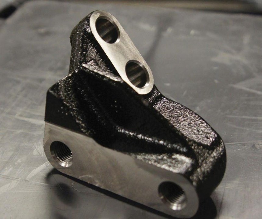
Understandably, it took an unusual set of circumstances to prompt the shop to adopt its first high-production VMC cell. Although most machining cells are in place for about 5-7 years, some jobs run longer. That was the case for the machining of an automotive engine stiffener bracket casting, a process that, by early 2015, was in dire need of an upgrade. Meanwhile, a DMG MORI Duravertical VMC had been sitting idle after the conclusion of a job with volumes too low to justify a dedicated HMC and robot, but too high for the company’s separate low-volume and prototyping divisions. Faced with the prospect of re-engineering the stiffener bracket job anyway, the team saw an opportunity.
Just maybe, Mr. Klint and his colleagues reasoned, the VMC could come close enough to the efficiency of an HMC to justify moving the stiffener bracket there rather than investing in an entirely new cell. In turn, proving that this could be done would open the door to using VMCs for other work as well. “We wanted to see how far we could go down this path until we hit a roadblock we couldn’t overcome, and that hasn’t happened yet,” he says, noting that the shop has installed six more VMC cells since then. “We’ll certainly install more horizontal cells moving forward. But we’ve also shown that verticals can be a key tool when it comes to staying competitive.”
Minding Seconds and Cents
Vickers Engineering’s success with its seven VMC cells speaks for itself. Still, Mr. Klint emphasizes that making up for the lost flexibility of an HMC’s indexing tombstone—that is, doing everything possible to minimize downtime in order to meet cost and cycle-time targets—took significant time and energy as well as all the ingenuity that the automation team could muster. The original cell for the stiffener bracket provides a prime example of the lengths to which the team goes to wring every last cent and every fraction of a second from its new VMCs.
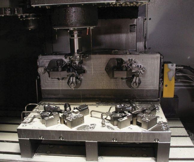
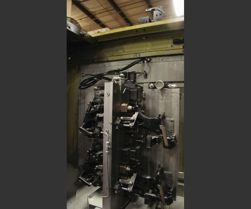
This particular part is machined in two clamping configurations. As shown on the next page, the VMC’s work envelope is large enough to comfortably accommodate four fixtures, two for each load (two A-side loads and two B-side loads). Experimentation led the team to abandon efforts to use all of the fixtures at once, as they might with a horizontal machine. Unloading two finished parts from the B-load fixtures, transferring two in-process parts from A-load fixtures to B-load fixtures, and loading two fresh castings kept the door open (and the spindle stopped) for too long. Rather, the crew determined that the best way to minimize spindle downtime would be to machine only two parts per cycle: one in an A fixture and one in the B fixture on the opposite side of the workzone (that is, catty-corner from the A fixture).
Once A-side and B-side machining on those parts is complete, the robot arm uses a twin-station gripper to bring in two fresh castings. The basic routine is place, pick, place, pick. More specifically, the robot first deposits a fresh casting into the open A-side fixture, then moves over and uses the same, now-unoccupied clamping station to pick up the already-machined part from the adjacent A-side fixture (place, pick). Then, it rotates 90 degrees and repeats the same process for the B-side fixtures. Now loaded with the two machined parts, it moves out of the workzone. The finished part (from the B-side fixture) goes to a conveyor leading out of the cell. The in-process part (from the A-side fixture) is deposited in a nesting fixture outside the machine, where it’s held in the proper orientation for loading in the open B-side fixture during the robot’s next cycle. Thanks in large part to this strategy, each interruption for loading/unloading amounts to only 7 seconds, beating the initial goal of 8 seconds. Compared to the dated, previous process, costs per piece were reduced from 31 to 18 cents.
Although every new job presents its own process engineering challenges, this first experiment taught the team a number of lessons that they’ve applied to every new VMC job since. Here’s a look at some of the key elements of the company’s strategy for making sense of vertical automation:
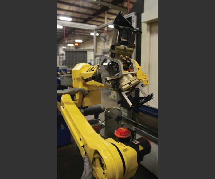
Faster ‘bots, faster doors. Keeping robot interruptions to 7 seconds on that first VMC cell took more than just creative engineering. In a practice that has been duplicated on all subsequent cells, the company opted for the lightest, smallest, and by extension, the fastest robot arm possible for the job: a M-10iA from FANUC Robotics with load capacity of 10 kg. That’s a contrast to the older horizontal cells, in which the ability to machine during loading/unloading cycles made robot capacity a greater priority than speed (hence the decision to standardize mostly on the relatively robust M-710iC, which offers 50-kg capacity).
To take full advantage of this speed, the automation team has replaced a side panel on each Duravertical with a new door that’s assembled in-house. Operated via an air cylinder with a programmable logic controller (PLC), these custom doors take only 0.8 second to open or close, compared to 1.5 seconds for the factory model.
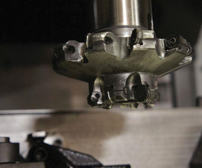
Custom cutters. The company’s first VMC cell never would have been able to compete with a horizontal configuration without two special geometries from Seco Tools. One is a back-chamfering cutter, a tool that approaches through one end of a hole to cut a chamfer surrounding the opening on the other end. The other custom tool, depicted on the next page, performs face milling and slotting operations on two different part faces simultaneously. Both tools share the same primary advantage: They help make up for the lost flexibility of an HMC by combining operations previously performed by multiple cutters, thus minimizing both tool changes and the number of required clamping configurations.
Leveraging gravity. Fortunately, workholding is one of the few aspects of the process that tends to be less complicated with a vertical, says Robert Kracker, a manufacturing engineer who works on the automation team with Mr. Klint. One reason is that once the cycle starts, gravity becomes a VMC’s ally, adding rigidity and firmly anchoring workpieces that might otherwise extend into thin air and require balancing with spring clips and toggles. To further press this advantage, vertical cell operators have made a habit of extending parts as far off the work table as possible. This reduces the distance—and time—required for the spindle to reach the workpiece while also improving rigidity, especially in extended-reach situations.
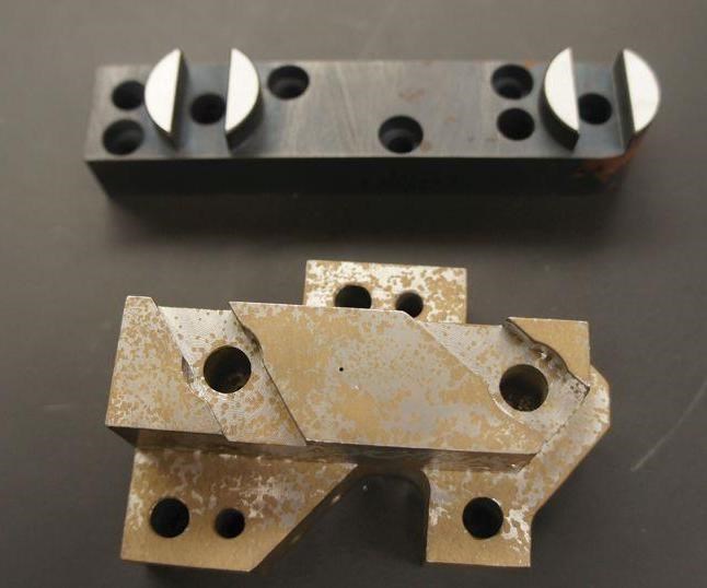
Granted, chip evacuation is always a particular focus when designing vertical fixtures, Mr. Kracker says, citing the practice of surrounding locating pin interfaces with counterbores and channels that provide pathways for coolant and chips to flow harmlessly away (see the picture on page 91). Overall, however, the relative simplicity of vertical workholding makes it easier to develop fixtures that help simplify robot motion and avoid misloads, Mr. Kracker says. This is particularly important when parts must move through multiple stations, including some outside the machine. For instance, the nesting fixture on the first VMC cell leverages gravity and various locating points to ensure the part fits only if oriented correctly for placement in the B fixture on the machine table. “The basic idea is to create a funnel—to have the part fall naturally into the fixture and only fit one way,” he says.
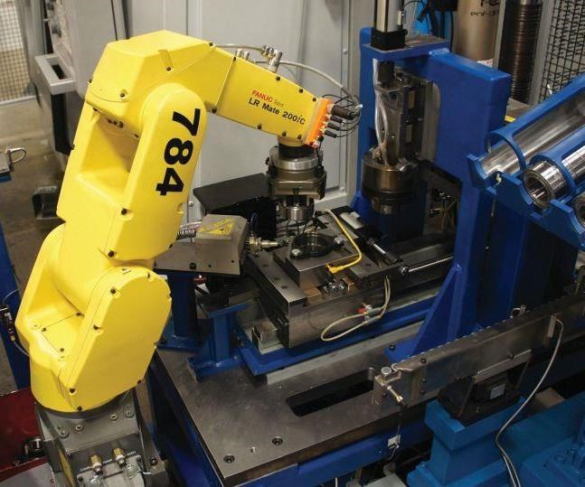
More sophisticated grippers. Engineering another variety of workholding—robot end effectors—isn’t so simple. Without the inherent flexibility afforded by an indexing tombstone, the team has been forced to think beyond end-of-arm tooling that grips parts in the same way on the same clamping locations every time.
That’s the case even for the single VMC on the floor that offers more than three axes. Without a fourth-axis rotary table, this machine could never access all of the part in only two clamping configurations on two dedicated fixtures. Even so, it took an innovative gripper design to ensure the robot arm could complete all needed transfers—loading a raw casting, unloading the finished part and moving the in-process part to the next fixture—without creating too much downtime, Mr. Kracker says. As shown on page 84, each of the gripper’s three stations is dedicated to one of these tasks, with the end effector rotating as needed in 180-degree increments. Although the in-process gripper and final-part gripper clamp on the same hole pattern, they interface with that pattern from opposite sides of the part. The fact that the hole pattern would be slightly offset if the two parts were to be laid atop one another complicated engineering, but it also helped prevent misloads, he notes.
As is the case with other vertical cells employing multifunction grippers, each station and each individual finger is clearly labeled to ensure proper assembly if components need to be replaced. Working with VMCs also led the engineering team to shave a few tenths of a second from the safety check that ensures parts are held securely before the robot moves away from the staging area, nest or fixture. Just like those in the older, HMC-based cells, VMC cell grippers fire a shot of air that triggers a sensor upon impact with the workpiece, and robot motion begins as soon as the PLC receives that signal. The difference is that on the new VMC cells, there’s no delay between the closing of the clamping mechanism and the safety check. “It’s like a stop sign instead of a stoplight,” Mr. Klint says.
CNC and programming tweaks. Although every cell is different, certain time-saving strategies are ubiquitous. For example, all DuraVertical VMCs come standard with a preset tool-change position—a “safe spot” for the spindle that minimizes the risk of interference when the automatic toolchanger makes the swap. Although that can be a boon for most general machining applications, every fraction of a second devoted to a tool change can mean the difference between success and failure on a VMC cell at Vickers Engineering, Mr. Kracker says. That’s why the team modifies this factory setting for every new machine, customizing tool-change positions and, in some cases, even adding more positions to minimize traverse time. Careful engineering and software simulation have so far proven
sufficient to avoid any problems.
Another tweak has reduced the time required to “teach” a robot; that is, to manually jog it through its programmed routine. Consider that for part pickup alone, this requires logging X, Y and Z coordinates for as many as 30 individual workpieces stations in each staging drawer. This can be time-consuming not only during initial cell setup, but also whenever a robot must be re-programmed for any reason (maintenance that requires removing and reinstalling end-of-arm tooling, a knocked fixture, etc.). To alleviate this burden, the team now uses offsets instead. Returning to the example of part pickup, each drawer has its own coordinate frame, the robot is jogged only to a central location, and the PLC calculates the locations of the rest of the stations based on that single point. In addition to saving time, this strategy has proven more reliable than manually jogging the robot because there’s less risk of error, Mr. Kracker says.
Always Worth the Effort
The work involved with engineering a vertical cell might seem overly daunting, no matter how significant the cost savings. Nonetheless, Mr. Kracker and Mr. Klint insist that experiments like this can pay dividends even if they don’t work out. For instance, the aforementioned tweaks to robot “teach” routines would save time regardless of whether the company had ever adopted VMC cells. The case is the same for various other changes catalyzed by that transition, including the decision to standardize on a single interface for all cell-controlling PLCs. Likewise, with a move to use more macros and subprograms—which can often be adapted for different cells later—in place of lengthy, step-by-step coding.
In any case, they and the other members of the automation integration team thrive on such work. Indeed, the very existence of this team reflects a view shared all the way up the chain of command: Vickers Engineering’s true competitive edge is not just the depth of its engineering knowledge and expertise, but also its creativity and its willingness to question established practices. “The best way to get us to try something is to tell us it can’t or shouldn’t be done,” Mr. Klint says.
Related Content
Inside the Premium Machine Shop Making Fasteners
AMPG can’t help but take risks — its management doesn’t know how to run machines. But these risks have enabled it to become a runaway success in its market.
Read MoreUsing the Toolchanger to Automate Production
Taking advantage of a feature that’s already on the machine tool, Lang’s Haubex system uses the toolchanger to move and store parts, making it an easy-to-use and cost-effective automation solution.
Read MoreLean Approach to Automated Machine Tending Delivers Quicker Paths to Success
Almost any shop can automate at least some of its production, even in low-volume, high-mix applications. The key to getting started is finding the simplest solutions that fit your requirements. It helps to work with an automation partner that understands your needs.
Read MoreIncreasing Productivity with Digitalization and AI
Job shops are implementing automation and digitalization into workflows to eliminate set up time and increase repeatability in production.
Read MoreRead Next
5 Rules of Thumb for Buying CNC Machine Tools
Use these tips to carefully plan your machine tool purchases and to avoid regretting your decision later.
Read MoreRegistration Now Open for the Precision Machining Technology Show (PMTS) 2025
The precision machining industry’s premier event returns to Cleveland, OH, April 1-3.
Read MoreBuilding Out a Foundation for Student Machinists
Autodesk and Haas have teamed up to produce an introductory course for students that covers the basics of CAD, CAM and CNC while providing them with a portfolio part.
Read More



.jpg;maxWidth=300;quality=90)


