Tying It All Together
This combination product line manufacturer and job shop is a classic example of an environment that calls for a fully integrated CAD/CAM system.
Share


Takumi USA
Featured Content
View More
Autodesk, Inc.
Featured Content
View More
There are an awful lot of CAD/CAM systems from which to choose, and many a shop has wondered which is the best. But there's no absolute answer to that question, because so much depends on the specific manufacturing environment. The answer for a job shop that is mainly programming parts to customer specifications, for instance, is entirely different than that for a product line manufacturer that is doing lots of design work.
If you're just cranking out NC code all day, then a hard-core CAM system is probably what you're after, something that can quickly create efficient tool paths and that has strong file translation capabilities. But you'll still have to decide whether your work is more oriented toward 2- and 2½-axis production machining or full 3D work, as optimal systems for these two cases will probably not be the same.
If you're mostly concerned with designing things—be it product components or production tooling—then you're looking for strong CAD functionality. You want the ability to quickly create and edit geometry, generate dimensioned drawings and perhaps to create well-detailed design files for downstream manufacturing applications.
In both of these cases—the strictly CAM or CAD environment—it probably doesn't matter a whole heck of a lot about how well your system supports the other function. Give designers the best CAD tools, manufacturers the best CAM tools, and let IGES or other translators bridge the gap between them.
But what if you do a bit of everything? That is, what if the same person must move quickly from design to manufacturing functions and then back again on a daily or perhaps even hourly basis? In that case, or in the case where CAD and CAM functions are tightly integrated in a concurrent engineering environment, then other issues come to the fore. And a highly integrated CAD/CAM system starts to make an awful lot of sense.
The ability to move deftly between design and manufacturing functions is precisely the concern of Urschel Manufacturing (Scottsdale, Arizona), a company that started out as a job shop but then developed a product line of its own. Urschel needs both to design efficiently and to manufacture efficiently, moving quickly from concept to prototype to an optimized production process—and with only a three-man CAD/CAM department. Here's how they accomplish that task.
The Company
A quick look at the business will help explain Urschel's CAD/CAM requirements. According to engineering and quality control manager Lloyd Eason, the company was founded in 1986 by Scott Urschel to machine parts mainly for Dillon Precision, a well known manufacturer of ammunition reloading equipment. Urschel started by machining relatively simple fixture-like "shell plates" and then moved on to more complicated parts, including a number of castings. And while additional job shop work was gradually brought into the mix, this one customer accounted for the majority of the business.
But over time Mr. Urschel grew increasingly convinced that the company could successfully become more diversified by developing a product line of its own. A water sports enthusiast, Mr. Urschel found his first major opportunity ten years ago on a jet ski—those motorcycle-like personal watercraft made by the likes of Sea Doo, Yamaha and Kawasaki, which zip across the water at speeds in excess of 60 mph. The first product was an aftermarket steering system designed initially for high performance racing craft (and later adopted by many recreational boaters), and so the "U.M.I. Racing" line was born. Urschel went on to broaden the line with more steering systems, water intake grates, finger throttles and other components. Then two years ago, Urschel introduced a line of aftermarket parts for Harley-Davidson motorcycles including forward foot controls and pegs, "triple tree" front suspension brackets, and many other accessories.
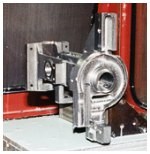
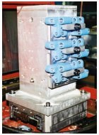
Several hundred different parts and assemblies have been developed at Urschel over the last few years, the majority of which also have been introduced into the company's machining operations alongside the existing job shop work. (All told, there are more than a thousand active part programs in the shop.) The product development process for each machined item in the U.M.I. line includes moving through a prototyping stage and then on to production machining, much of which is done in an FMS environment, and virtually all of which is optimized after the initial production begins.
So from a CAD standpoint, Urschel has had to secure the ability to rapidly move from a sketchy initial concept to detailed drafting, incorporating changes at multiple points along the way, and in many cases designing production tooling as well. As for CAM, they must be able to create the initial prototype programs quickly and then later have the control necessary to generate machining processes that are both efficient and reliable enough for unattended operation. Sometimes that involves design modifications to aid in manufacturability; modifications that may well be made after they begin to build fixturing or even after they see how the part actually runs in production.
The Design Process
This high degree of interaction between design and manufacturing functions is precisely why an integrated CAD/CAM system makes so much sense for Urschel. The one they have chosen is Anvil Express from Manufacturing and Consulting Services (MCS), Inc. (Scottsdale, Arizona), a product that is particularly representative of some of the more interesting time-saving functionality that is now coming to relatively inexpensive PC-based CAD/CAM systems.
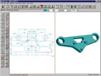
Perhaps the most critical component of this and other integrated systems is the ability to work from a single geometric workpiece file, and to work back and forth between CAD and CAM applications without having to deal with file translations. And particularly important to Mr. Eason's time-critical interactions with this core product data is the ability to quickly access all the CAD and CAM functionality from the top of a single interface, and to draw upon standard but easily customizable templates that automate much of the redundant drafting and NC programming tasks.
A look at the product development process helps explain why the close integration of such a wide variety of functionality is so important. While the notion of a successful product design springing from the back of an envelope has become a bit of a cliché, it's not so far afield from how the design process often works at Urschel. Typically, one of the company's principals will come to Mr. Eason with an idea, and together they will sketch out the required physical attributes of the product. Then a member of the design team will go into CAD and do the initial drafting of the new design. This file may at first be used just to help them visualize the physical characteristics of the part, or perhaps as job documentation for the manual machining of a prototype. But it will ultimately prove to be the platform on which the rest of the design and manufacturing process will be built.
Critical to making the drafting process efficient, says Mr. Eason, is having an interface that gives him ready access to a range of drafting tools. And particularly important is the ability to get at modal commands, where much of the company's preferred drafting methods are captured and automatically applied when required.
More specifically, if a design is being generated from scratch, he can create a new file with a whole regimen of company-standard formatting commands in place—for instance, just geometry on one level, critical dimensions on another level, manufacturing instructions on another level, and so on. Applying such a discipline has two major advantages. First, it saves the unproductive time it would otherwise take to set up a new design file. And later on, it will make the file much easier to work with when it comes time to make changes. "You know right where everything is," says Mr. Eason. "Also, the drafting modals are all on one screen, so when you have to change one, you don't have to go through several levels of menu picks, or remember precisely where in the system to find it."
Quick access to various geometry construction tools is important too. While the bulk of Mr. Eason's work can be accomplished in 2D and 3D wireframe, he occasionally requires higher level construction techniques, and can he move right into surfacing or solid modeling when the situation calls for it. Moreover, all of these construction tools can be used on a single model if necessary. Working within a single drafting environment is all the more important here because the common interface and logic that runs throughout the system allows Mr. Eason to be productive with construction techniques that he uses only once in awhile, and thus is not afforded the opportunity to keep his operational skills as sharp as with those tasks he performs every day.
It is, in essence, a lot of tools in one familiar bag, and he is free to choose whichever one works best for the job. Mr. Eason believes that the best tool is generally the simplest, which is why he still tends to work mostly in wireframe for 3D parts. For full visualization—which can be extremely useful in the cosmetically conscious industry Urschel serves—he is more inclined to use 3D shading rather than going the extra step of creating a solid model. For the most part, though, he creates only the geometry he needs. Should further detailing be required down the road, it will be easy enough to go back and edit the model when the time comes.
Moving Into Production
For the machined parts, sooner or later the design model is going to become the basis for an NC part program. That's sooner if the prototype is cut on one of the shop's CNC machines, later if it's cut manually, but not too much later. Common practice at Urschel is to make a single prototype, test it, incorporate necessary changes, and then move right into production.
While this one-step prototyping process might sound a bit risky by some conventional measures—both from pure design and manufacturing perspectives—Urschel's flexibility in CAD/CAM makes it quite practical because they need not freeze the design file in order to get a part into production. Indeed, they expect manufacturing and design issues to impact upon one another, and insist upon maintaining the ability to quickly make part or process changes so long as there is still the opportunity to make meaningful improvements to either.
How does CAD/CAM technology support this continuous improvement effort? For one thing, it is very easy for Urschel to make changes to the design model after a part program has been generated. If they were dealing with separate CAD and CAM systems, a file would be generated in CAD, passed through a translator to CAM (with some geometry cleanup invariably required), and then the part program would be generated. Then if a design change came, they would have to go back to the original CAD file (if they want the workpiece documentation to be geometrically consistent with the part program), execute the change, repeat the translation and then perhaps also repeat a significant portion of the NC programming process. With a fully integrated system, however, both CAD and CAM work directly from the same geometry. In many cases, a geometry change can be executed and the tool path can then be regenerated virtually automatically.
But not in all cases. If, for example, an entirely new feature is added to a workpiece—say, a pocket—then that feature will have to be programmed from scratch. However, by Mr. Eason's estimation, it is here that easily accessible modal pages play an even more useful role than they do in CAD. Behind each machining operation—pocketing routine, drilling cycle, fly cutting routine, and so on—is a whole raft of modal commands that control virtually every aspect of the tool path creation logic. In our new pocket, for example, the modals control not just feeds, speeds and stepovers, but also tool engagement and retract methods, cutter path sequences and more. While this degree of control can require quite a lot of interaction the first time each tool path mode is set, the entire group of settings can be saved as a template—that is, a generic machining strategy—and then applied automatically to subsequent workpieces once the specific geometry of the new feature is defined.
So when Mr. Eason has to add the pocket to a previously programmed workpiece, all he has to do is go directly into the CAD geometry and make his edits, apply an appropriate pocketing template to the new geometry, and specify where the routine should fall in the existing program. Both the CAD drawings and the part program are updated accordingly. All that's left to do is post process the new program and print out the drawings for shop documentation, and the revised job is ready to run.
This near immediate access to design and NC process data also facilitates a surprising degree of machining process optimization that happens on a regular basis. Using standard templates will get jobs up and running quickly. But once Urschel's machinists see how those process plans play out on a real machine tool, they can usually find a way to improve them. If it's a simple matter of adjusting feeds and speeds, those edits may be made right on the shop floor. But process improvements may also be made by editing the modal settings to apply a more efficient machining strategy. Also, some product design changes may be executed in order to improve the machining process—adding a boss, for example, to provide a better workholding surface, or adding some reinforcement to reduce chatter or workpiece deflection. Or maybe they see that by changing a radius or two, a tool change can be completely eliminated from the program. Perhaps that radii modification will allow the roughing and finishing routines for a pocket to be combined into a single tool path once Mr. Eason makes a few changes to the cut sequence and material engagement technique.
All of these midcourse adjustments are practical because Urschel's programmers have ready access to both the design and manufacturing data, and have very few barriers—technical or organizational—to prevent them from executing modifications wherever and whenever they are warranted. And that gives this company an enviable combination of production flexibility, speed and control.
Related Content
5 Tips for Running a Profitable Aerospace Shop
Aerospace machining is a demanding and competitive sector of manufacturing, but this shop demonstrates five ways to find aerospace success.
Read MoreERP Provides Smooth Pathway to Data Security
With the CMMC data security standards looming, machine shops serving the defense industry can turn to ERP to keep business moving.
Read More6 Machine Shop Essentials to Stay Competitive
If you want to streamline production and be competitive in the industry, you will need far more than a standard three-axis CNC mill or two-axis CNC lathe and a few measuring tools.
Read MoreContinuous Improvement and New Functionality Are the Name of the Game
Mastercam 2025 incorporates big advancements and small — all based on customer feedback and the company’s commitment to keeping its signature product best in class.
Read MoreRead Next
5 Rules of Thumb for Buying CNC Machine Tools
Use these tips to carefully plan your machine tool purchases and to avoid regretting your decision later.
Read MoreBuilding Out a Foundation for Student Machinists
Autodesk and Haas have teamed up to produce an introductory course for students that covers the basics of CAD, CAM and CNC while providing them with a portfolio part.
Read MoreRegistration Now Open for the Precision Machining Technology Show (PMTS) 2025
The precision machining industry’s premier event returns to Cleveland, OH, April 1-3.
Read More




.jpg;maxWidth=300;quality=90)


.jpg;maxWidth=300;quality=90)
